D-serie level 1 EN.pdf - 第150页
SITEST Overview SITEST Overview of Settings and Calibration Work S tuden t Guide Advanced Level 1 SIPLACE D-Series SITEST EN 05/2007 9-6 calibr ations fro m th e l e ft to th e r i g h t reasons for calibr ations Z ero p…
SITEST
Overview of Settings and Calibration Work Overview SITEST
Student Guide Advanced Level 1 SIPLACE D-Series
EN 05/2007 SITEST
9-5
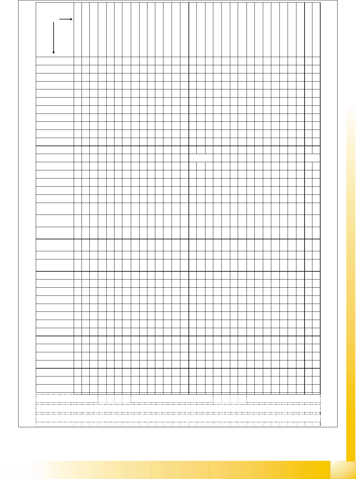
adjustments sequence
from the left to the right
reason for
adjustments
a
dj
us
t
reso
l
u
t
u
i
n pos
iti
on measur
i
ng
system Star-axis C&P-head
Z
ero po
i
n
t
corr.
Z
-ax
i
s
C&P
-
h
ea
d
(automatically done at reference)
Mount the place.star with power sup
ply and zero point gauge
Zero point corr. star-axis C&P-head
a
i
r
ki
ss supp
l
y
h
ose
0
.
7
mm a
b
ove
ballrace surface
a
i
r
ki
ss
t
u
b
es a
t
segmen
t
s
0
.
1
-
0
.
2
mm clearance to DP-encoder
Adjust 1,5mm clearance track signal
encoder DP-Axis to segment glas disc
Adjust motor position to 0,2 mm
clearance plunger to housing
Test upper end stop position Z-axis
Adj
us
t
th
e
1
.
3
mm c
l
earance
LB
bottom to the sleeve
Check belt tensions of refering axis
(different tension DLM1/2 C&P heads)
Align positionand adjust distance
(0.4mm) track signal encoder
Test track signals and Zero pulse at
the X / Y - axis
Set CAN-BUS address (gantry 1/2)
and other DIP-switches
Zero point corr Z-axis TWIN-head
Zero point corr. D- turning axis TWIN-
head
E
n
t
er
b
as
i
c
F
orce sensor parame
t
er
TWIN-head
Adjust the Anti-Crash-board(s)
Adjust the air kiss at placement-
and pick up (reject) circuit
Adjust the slow transport speeds
Adjust the PCB light barrier sensors
Adjust the LASER beam direction
Adjust the clamping (Piezo) sensor
Check & Adjust the clamping/
unclamping time o lifting table
Adjust the clamping height for PCB
(94,2 -0.2mm / 94.4 + 0.1 mm
Teach / store !!! New defaultposition for
fixed con. side (SIEMENS FSE only)
Download refering Firmware
(SIEMENS
FSE only)
Check & Adjust belt tension at the
refering PCB-conveyor
Check axis dynamic of referering axis
Check vacuum system if it is sealed
Replace stepper motor of
vacuum air kiss
D/X
/HF
Replace air kiss unit
D/X
/HF
Replace light barrier
bottom on Z-axis
D/X
/HF
Replace the motor / belt of
the Z-axis C&P
D/X
/HF
D/X
/HF
D/X
/HF
D/X
/HF
Replace the DP-station
D/X
/HF
Replace the track signal
encoder of the DP-station
D/X
/HF
D/X
/HF
Replace the vacuum
distributor
D/X
/HF
mech. Influence/Replace
the air kiss supply hose
D/X
/HF
Dismount/replace the
placement star DLM
D/X
/HF
D/X
/HF
D/X
/HF
D/X
/HF
D/X
/HF
D/X
/HF
Replace the star motor
D/X
/HF DLM
D/X
/HF
D/X
/HF
D/X
/HF
D/X
/HF
Replace C&P-head
D/X
/HF
D/X
/HF
D/X
/HF
D/X
/HF
D/X
/HF
D/X
/HF
D/X
/HF
head modularity (C&P
head exchange)
D/X
/HF
D/X
/HF
D/X
/HF
D/X
/HF
D/X
/HF
D/X
/HF
D/X
/HF
Replace Segment(s) of
TWIN-head
D/X
/HF
Replace Vision board at
gantry or for stationary
D/X
/HF
D/X
/HF
Replace C&P-Head
adapter board
D/X
/HF
D/X
/HF
Replace 'SLIO' board(s)
D/X
/HF
D/X
/HF
Replace Head interface
board (Head board)
D/X
/HF
Replace the
Portalinterface (conv.
D/X
/HF
D/X
/HF
D/X
/HF
Mechanical influence on
parallelity of fixed con.
side '1' to conv. frame
D/X
/HF
(*)
Mechanical influence on
straightness of fixed con.
side '1'
D/X
/HF
Set Single conv. mode for
dual conv. only for pure HF-
lines! Ask Siemens Service
D/X
/HF
Replace the encoder
X- / Y-axis
D/X
/HF
****
Count errors X- / Y-axis
(after cleaning)
D/X
/HF
D/X
/HF
Adjust conveyor speed to
the needs of customer
Placement process
D/X
/HF
D/X
/HF
Exchange Transport
control unit
D/X
/HF
Replace the light barrier for
PCB conveyor
D/X
/HF
D/X
/HF
Replace the LASER PCB-
Stopper
D/X
/HF
Replace clamping sensor
D/X
/HF
some exchange at lifting
table unit
D/X
/HF
Replace the conveyor
motor
D/X
/HF
Replace conveyor belt
D/X
/HF
Replace conveyor belt
guideance
D/X
/HF
Exchange control unit
Component table
D/X
/HF
Exchange control unit
Tape cutter
D/X
/HF*
Exchange control unit
coplanarity unit
D/X
/HF *
D/X
/HF
Exchange MVS 340
Vision controller
HF
**
Exchange Axis controller
board
D/X
/HF
Replace the Servo
amplifier board
D/X
/HF
Replace Anti Crash board
(X)
/HF
X/HFm
D1 & D3/X/HF
mit TWIN
D3/X/HF mit
TWIN
****
SIEMENS SERVICE LEVEL ONLY
for Single conveyor mode on Dual conv. We able to open to 410mm board width
(edit maximal width conv .1 to 410000) in REAL.MA without moving the fixed rail which is alligned to HS/S / F machines (for larger width change 'Hoehenverm_Y PG 1/2' too the deviation the conv. side is
***3x (BIO's /Appl.1 and different Appl. 2 ) per board
** automatic Download at loading 1st Feeder set up /1st
Boot
(0) The tension of the Z-belt at DLM1/2 C&P-heads adjusted to 280 +/- 10 Hz; the 10.000/8.000 C&P head Z-Belt is adjusted to 185 Hz.
* 2 Jumper code 4 possible addresses
SITEST
Overview SITEST Overview of Settings and Calibration Work
Student Guide Advanced Level 1 SIPLACE D-Series
SITEST EN 05/2007
9-6
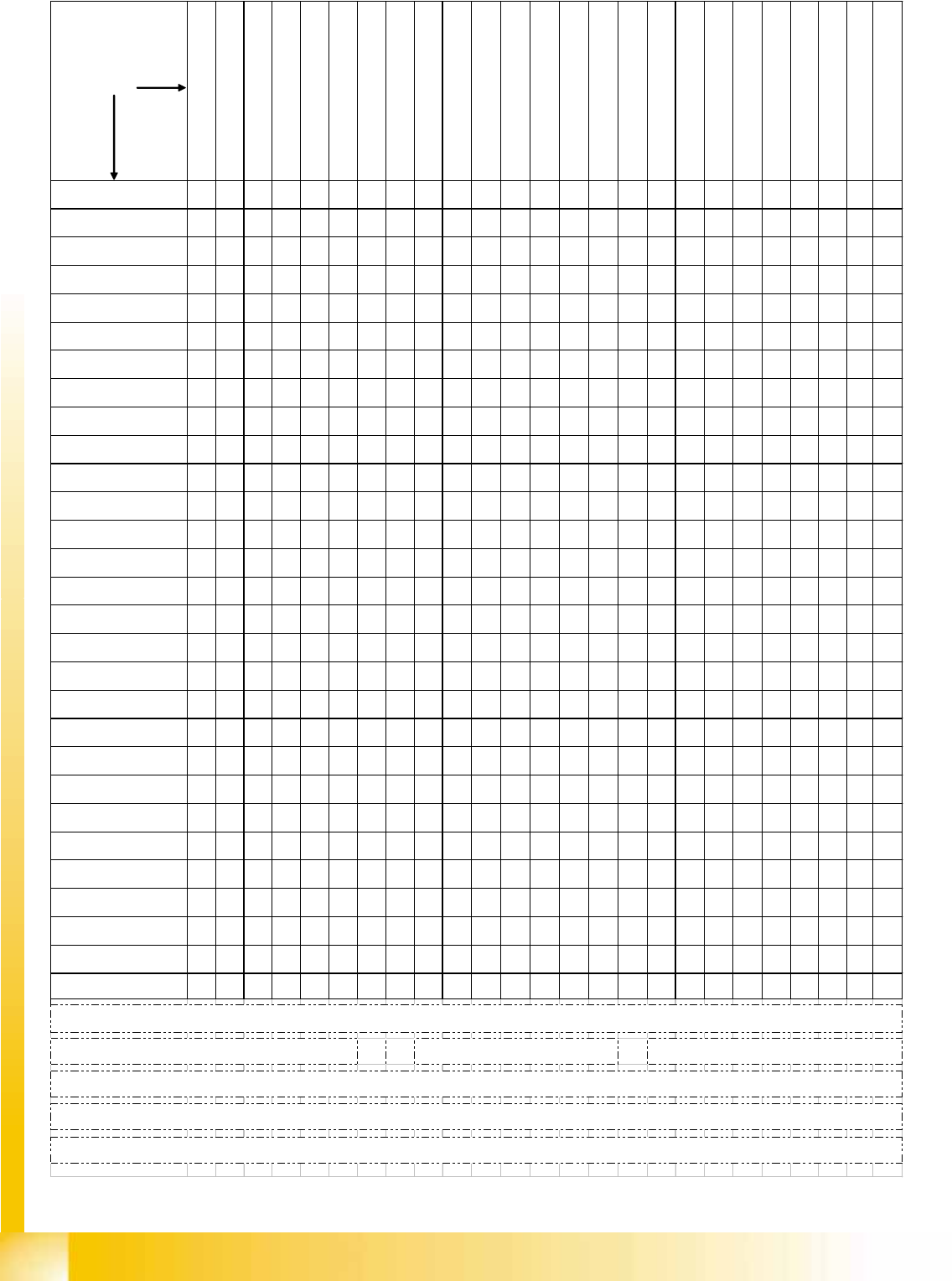
calibrations
from the left to the right
reasons for
calibrations
Zero point corr. star-axis C&P-head
Zero point corr. Z-/ D-axis and basic
force sensor parameter TWIN-head
Calibrate MA-zero point both gantries
of the Placement Area PAx
Calibrate PCB camera
Calibrate RV-head (include
component camera offset and
single measure ment segment offset
I (only for checking offset)
single measure ment segment offset
II (only for checking offset)
Calibrate TWIN Head IC-camera
Calibrate TWIN Head FC-camera
Calibrate coplanarity module (ILD
2200 1 D-version)
Calibrate Feeder area (for D1 WPC
is considered)
Calibrate fixed PCB-corner(s)
Calibrate moveable Conveyor Edges
(rail(s))
Calibrate calibration tool position
Calibrate TWIN-nozzle changer X/Y-
position
Calibrate TWIN-nozzle changer
Nozzle pick up height
Calibrate C&P-nozzle changer X/Y-
position
Calibrate C&P-nozzle changer Pick
up height
Calibrate vacuum TWIN head
Travel area X / Y axis
Execute PCB-Mappings
Execute RV-Mappings
Execute IC-Mappings
Fi
ne ca
lib
ra
ti
on
(if
p
l
acemen
t
accuraccy have to be increased at
Replace / remount PCB-
camera
D/X/
HF
D/X/
HF
D/X/
HF
D1&D3
/X/ HF
w TH
D1&D3
/X/ HF
w TH
D1&D3
/X/ HF
w TH
D/X/
HF
D/X/
HF
D/X/
HF
D1&D3
/X/ HF
w TH
D/X/
HF
D/X/
HF
Replace C&P-head
D/X/
HF
D/X/
HF
D/X/
HF
D/X/
HF
D/X/
HF
D/X/
HF
Remount C&P-head
D/X/
HF
D/X/
HF
D/X/
HF
D/X/
HF
D/X/
HF
Mechanical influence to the
segment guideance
D/X/
HF
D/X/
HF
New Star zero point
correction
D/X/
HF
D/X/
HF
D/X/
HF
compo-nent camera refer.
C&P head
D/X/
HF
D1&D3
/X/ HF
w TH
D1&D3
/X/ HF
w TH
D1&D3
/X/ HF
w TH
Replace / remount
placement star
D/X/
HF
D/X/
HF
D/X/
HF
Replace / remount Star
motor
D/X/
HF
D/X/
HF
D/X/
HF
Replace / remount
Segment(s) TWIN-head
D1&D3
/X/ HF
w TH
D1&D3
/X/ HF
w TH
D1&D3
/X/ HF
w TH
D1&D3
/X/ HF
w TH
D1&D3
/X/ HF
w TH
D1&D3
/X/ HF
w TH
D1&D3
/X/ HF
w TH
Replace / remount TWIN-
head IC-camera
D1&D3
/X/ HF
w TH
D1&D3
/X/ HF
w TH
Replace / remount TWIN-
head FC-camera
D1&D3
/X/ HF
w TH
encoder incremental scale
X/Y
D/X/
HF
D1&D3
/X/ HF
w TH
D1&D3
/X/ HF
w TH
D1&D3
/X/ HF
w TH
D1&D3
/X/ HF
w TH
D/X/
HF
D/X/
HF
Replace / remount LASER
PCB stopper
D/X/
HF
New teaching of fixed PCB-
conveyor side (fixed rail)
D/X/
HF
D/X/
HF
Conveyor mode change
Right <--> Left side fixed
D/X/
HF
D/X/
HF
Use Dual conveyor in Single
conveyor mode **
D/X/
HF
D/X/
HF
Switch Dual conveyor to
dual conveyor mode
D/X/
HF
D/X/
HF
zero point & calib. jig
position
D/X/
HF
D1&D3
/X/ HF
w TH
D1&D3
/X/ HF
w TH
D1&D3
/X/ HF
w TH
D/X/
HF
D/X/
HF
D/X/
HF
D1&D3
/X/ HF
w TH
D/X/
HF
D/X/
HF
Replace / remount
component table
Replace / remount
coplanarity module
D1&D3
/X/ HF
w TH
mechanical influence to the
gantry
D/X/
HF
D1&D3
/X/ HF
w TH
D1&D3
/X/ HF
w TH
D1&D3
/X/ HF
w TH
D/X/
HF
D/X/
HF
D1&
D3/X
/HF
Replace / remount nozzle
changer TWIN-head
D1&D3
/X/ HF
w TH
D1&D3
/X/ HF
w TH
Replace / remount nozzle
changer C&P-head
D/X/
HF
D/X/
HF
Recalibrate machine zero
point (all gantries of a
PA
)
D/X/
HF
D1&D3
/X/ HF
w TH
D1&D3
/X/ HF
w TH
D1&D3
/X/ HF
w TH
D/X/
HF
D1&D3
/X/ HF
w TH
D/X/
HF
Head modularity 6/12 C&P
D/X/
HF
D/X/
HF
D/X/
HF
D/X/
HF
D/X/
HF
D/X/
HF
D/X/
HF
D/X/
HF
XH/
HF
Head modularity
C&P->TWIN
D1&D3
/X/ HF
w TH
D1&D3
/X/ HF
w TH
D1&D3
/X/ HF
w TH
D1&D3
/X/ HF
w TH
D1&D3
/X/ HF
w TH
D1&D3
/X/ HF
w TH
D1&D3
/X/ HF
w TH
D/X/
HF
XH/
HF
Head modularity
TWIN -> C&P
D1&D3
/X/ HF
w TH
D1&D3
/X/ HF
w TH
D1&D3
/X/ HF
w TH
D1&D3
/X/ HF
w TH
D/X/
HF
XH/
HF
Exchange Transport control
unit
D/X/
HF*
First setup (at munich)
D/X/
HF
D1&D3
/X/ HF
wTH
D/X/
HF
D/X/
HF
D/X/
HF
D1&D3
/X/ HF
wTH
D1&D3
/X/ HF
wTH
D1&D3
/X/ HF
wTH
D/X/
HF
D/X/
HF
D/X/
HF
D/X/
HF
D1&D3
/X/ HF
wTH
D1&D3
/X/ HF
wTH
D/X/
HF
D/X/
HF
D1&D3
/X/ HF
wTH
D/X/
HF
D/X/
HF
D/X/
HF
D1&D3
/X/ HF
wTH
D/X/
HF
XH/
HF
Whole calibration of the gantry after head-or head front part disassembling if increased placement accuracy is expected or placement deviation is too high
For the 6 nozzle C&P-head we use 956 nozzles like for the 12 nozzle head.
With 956 nozzles is the lower end of the calibration tool exact in the focus level of the C&P-head component camera. We use 956 for DCA-camera option too.
NOTE !! Calibration of the HS / S / F machines have a different sequence because there is the calibration reference the component camera on the gantry.
Because of construction here, on HF is the reference is the PCB-camera.
* afterTeaching the fixed side 'Right conveyor'
** up to 410 mm Standard to the HS/S/F machines nothing to
calibrate. For larger dimensions on pure HF-

SITEST
Overview of Settings and Calibration Work Calibration
Student Guide Advanced Level 1 SIPLACE D-Series
EN 05/2007 SITEST
9-7
9.2 Calibration
Tools and SITEST
Calibration tool – general –
Version III not transparent is for HF/X/D machines with C&P6/12 and Twin/P&P Head [03010565-01]
(Version II transparent is for S/F/HS machines [00316308-03], calibration nozzle 920)
(Version for SST23 at X machines with C&P20 head [03034148-xx])
Nozzles – general –
Type 956, 517, 518, nozzle for ZPC of D-axis TH [03008862-03]
(C&P20 head: 1235)
Setting gauge for S tables
Board for calibrating the PCB conveyor width
2D coplan - (ILD2200) - calibration tool
SITEST, version 602.xx or higher
DANGER: RISK OF INJURY!
The gantry may move during some of the following procedures.
Therefore, before you begin with any of these procedures make sure that you and everyone else
stay physically clear of the travel range of the gantries.
X Also, sure, that no objects are in the way.
NOTE:
Before you begin with the calibration, you must reference the heads and the gantries.
During calibration, unused gantries will automatically be moved to their parking position.
To completely calibrate the machine, go to
Calibrate machine...
and select the
Calibrating
the entire machine
menu. This provides all the required calibration functions.