D-serie level 1 EN.pdf - 第92页
C&P6/12 Placement Heads Placement Procedure Air Blast and Vacuum Supply - Description S tuden t Guide Advanced Level 1 SIPLACE D-Series C&P6/12 Placement Heads EN 05/2007 6-12 6.1.10 Air Blast and V ac uum Supply…
C&P6/12 Placement Heads
Overview Vacuum Supply Overview
Student Guide Advanced Level 1 SIPLACE D-Series
EN 05/2007 C&P6/12 Placement Heads
6-11
6.1.9 Overview Vacuum Supply
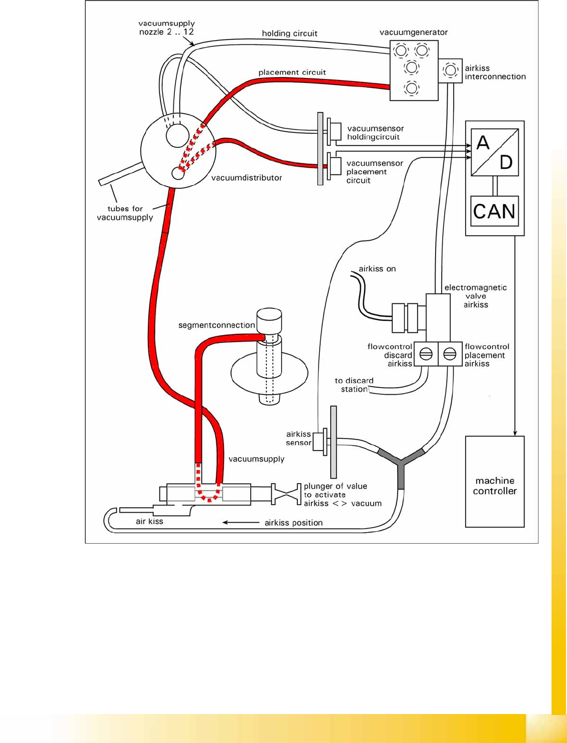
6-8: Overview of vacuum function
C&P6/12 Placement Heads
Placement Procedure Air Blast and Vacuum Supply - Description
Student Guide Advanced Level 1 SIPLACE D-Series
C&P6/12 Placement Heads EN 05/2007
6-12
6.1.10 Air Blast and Vacuum Supply - Description
The two diagrams show that there are 3 states for air supply to the segments.
Electromagnetic valves ON & valve plunger inside: air blast is present at the segment for placement
(reject).
Electromagnetic valves OFF & valve plunger inside: the segment is airtight i.e. it is cut off from the
air blast and vacuum supplies.
Valve plunger pulled (towards back): the connection to the vacuum supply exists, even if the
electromagnetic valve is switched on.
This function description illustrates that the valve plunger is the element with the greatest influence on
the placement and pickup reliability. It is therefore important to maintain this key part with the tools
specially developed for this purpose.
6.2 Placement Procedure
6.2.1 Working Position on Placement Head
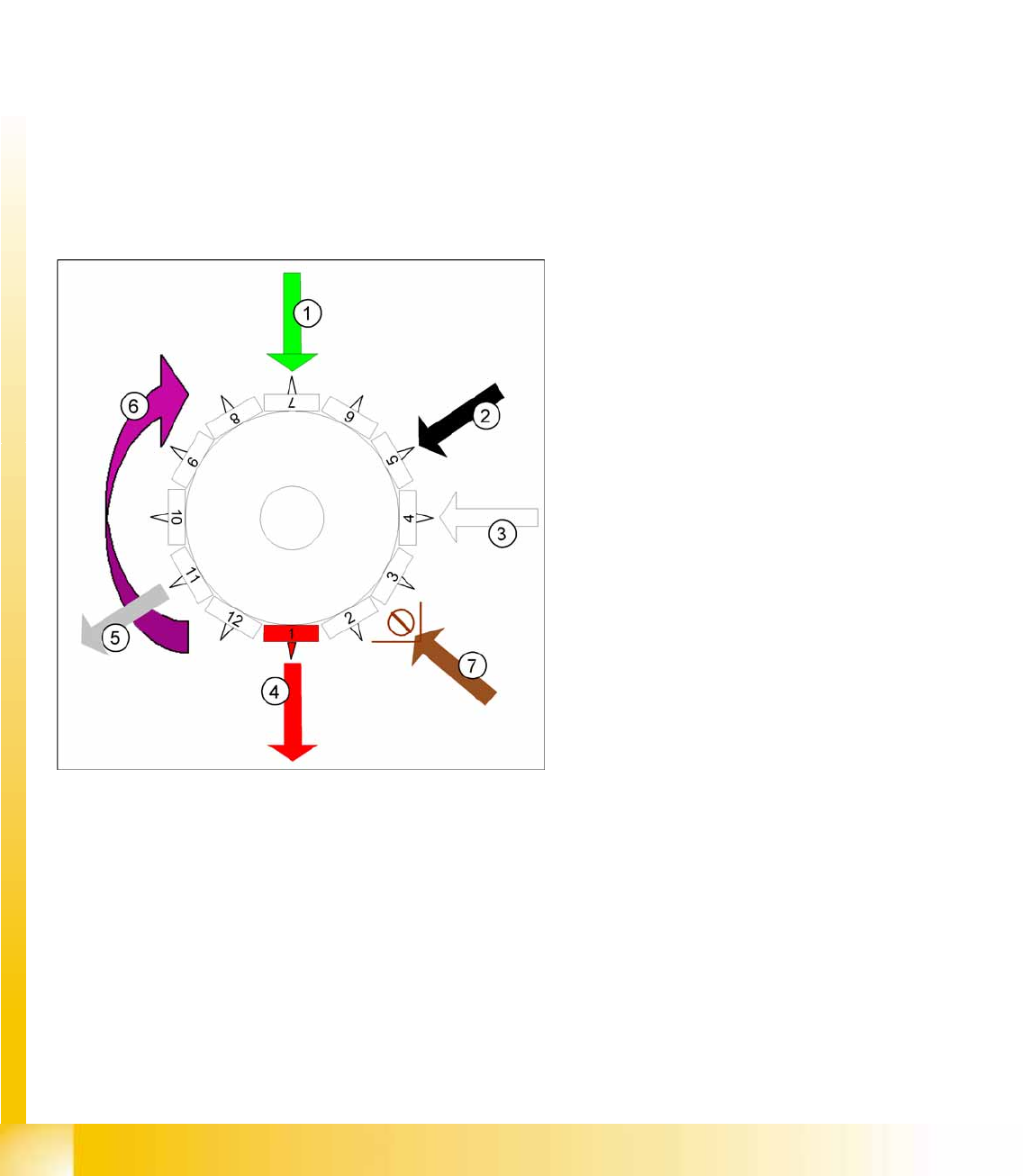
6-9: Working position on placement head
Legend
1. optical centering
2. Turning station / DLM2
3. Service position for segment: check/remove
the nozzles and sleeves
4. Pickup and placement station (reject station
for D1/D2 and D3)
5. Reject position for D4 machines
6. Direction of operation
7. Position of component sensor option (only
C&P12)
C&P6/12 Placement Heads
C&P12 in Basic Positon Star 15° Placement Procedure
Student Guide Advanced Level 1 SIPLACE D-Series
EN 05/2007 C&P6/12 Placement Heads
6-13
6.2.2 C&P12 in Basic Positon Star 15°
6.2.3 Boards – Position Recognition
Board position recognition is used to determine the exact position of the board in the machine (conveyor
--> placement area). There should be at least two fiducials on the board. These are then used to
calculated the X/Y position and the rotary angle of the board, in the conveyor system. A maximum of 3
fiducials can be programmed for position recognition. The fiducials should not be on the same line as
one another. In addition to determining the position of the board in the conveyor system, this 3rd fiducial
enables you to determine and correct any displacement within the board (jolted, stretched).
6.2.3.1 Temperature Compensation
In addition to board recognition, SIPLACE D-series machines perform temperature compensation with
the 2nd gantry in the placement area, through PCB position recognition. This compensates another error
source which could affect accuracy.
6-10: C&P12 in basic position star 15°
Star position:
Digits: 15000
Angle 15°
1° is equivalent to 1000 digits
This is the basic C&P12 setting. When the X and
Y axes are in the waiting position, the star axis is
rotated into this basic position (30° at C&P6).
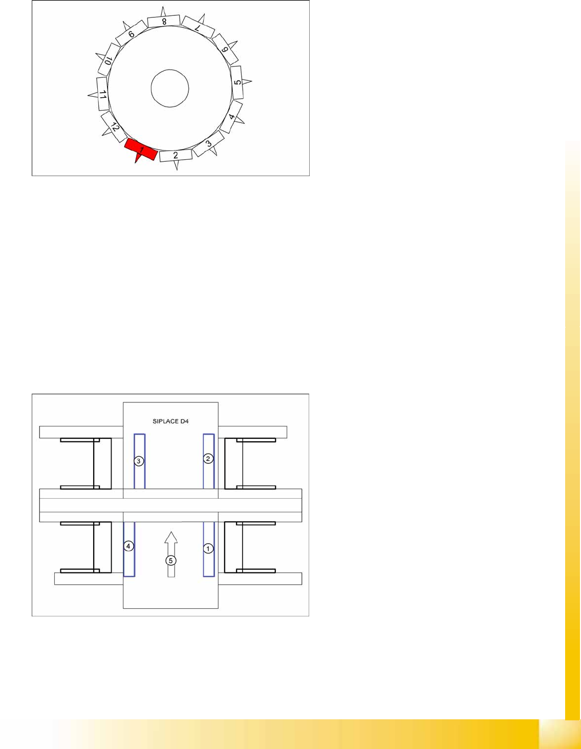
6-11: Board recognition in SIPLACE D4
Legend
1. Gantry 1
2. Gantry 2
3. Gantry 3
4. Gantry 4
5. Transport direction
Gantry 4: position recognition with max. 3
fiducials,
Gantry 2: position recognition with max. 2
fiducials, in PA 2 of D4
Gantries 1 and 3: Temperature compensation
by approaching the fiducials - a position
difference to gantry 4 or 2 is recognized by the
Vision system and is then taken into account and
compensated in the following placement
procedure.