D-serie level 1 EN.pdf - 第76页
Reference Run Reference Run ( D-Series) Repeating Measurement of Values During Placement S tuden t Guide Advanced Level 1 SIPLACE D-Series Reference Run EN 05/2007 5-8 5.1.5.2 Nozzle Length Measurement in the Component S…

Reference Run
Height Reference Run Reference Run (D-Series)
Student Guide Advanced Level 1 SIPLACE D-Series
EN 05/2007 Reference Run
5-7
5.1.4.3 Rotating the Nozzles into the 0 Degrees Starting Position
While the vacuum values are being measured, the turning station can rotate all segment sleeves into the
0° starting position.
Sequence:
X The star axis rotates all segments through the working positions.
X The turning station swivels in during vacuum measurement.
X The axis controller positions the relevant segment at the light-dark transition, which represents the
0 degrees position of the sleeves. (The long side of rectangular nozzles in the X direction.)
X – The turning station is swiveled out again by a CAN bus command .
5.1.4.4 Nozzle Scanning
While the vacuum values are measured, the camera tests the empty nozzles for contaminants.
Sequence:
X The star axis rotates all segments through the working positions.
X The component camera illuminates the nozzle and measures its outer and inner contours.
X If the nominal dimensions are not met, a "nozzle dirty" error message is issued.
The vacuum reference run is now finished.
5.1.5 Height Reference Run
5.1.5.1 Head Height Check and Nozzle Length Measurement
This part of the reference run is performed in sequence at the gantries of the relevant processing area,
as the X/Y height measurement position needs to be the same for both gantries.
Sequence:
X The gantry axes move the placement head over the height measurement position on the fixed
conveyor side.
X The Z-axis moves segment 1 down, as far as the end stopper.
X The Z.axis "height position" is read out of the Z-axis position counter.
X The Z-axis is moved up again, to the 0 position.
X This process is repeated for all the segments of the relevant placement head and then for the 2nd
gantry.
X A nozzle length error is issued if the values deviate by more than+/- 0.4 mm from the nozzle 1
measurement. The nozzle causing this error must then be replaced before starting placement
operations.
NOTE:
All measurement values are accepted for special nozzles in the X9X series.
Reference Run
Reference Run (D-Series) Repeating Measurement of Values During Placement
Student Guide Advanced Level 1 SIPLACE D-Series
Reference Run EN 05/2007
5-8
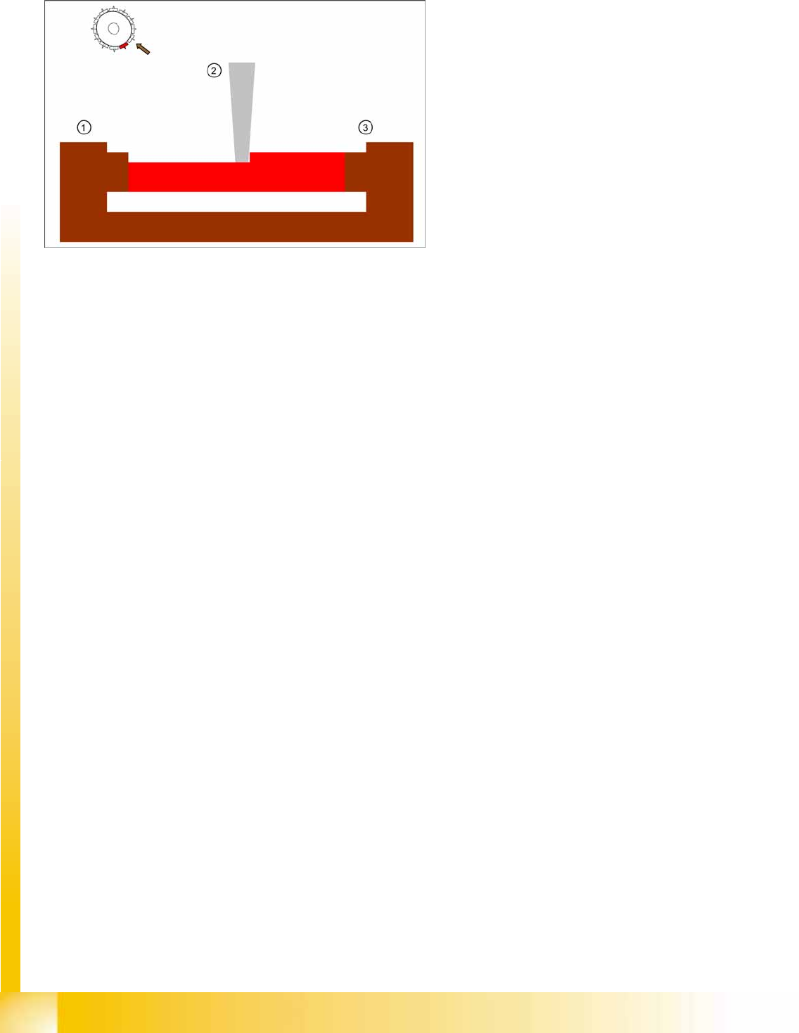
5.1.5.2 Nozzle Length Measurement in the Component Sensor
If the component sensor option is installed and configured on the C&P12 placement head, the MC will
issue a CAN bus command for nozzle length measurement to be performed in the component sensor,
provided the nozzle to be set up is long enough (for nozzles longer than 12 mm, appropriately longer
than a 915 nozzle).
X The shadow cast by the component sensor IR laser beam is measured during star rotation.
X The programming system prescribes the nominal parameters for dynamics, length and vacuum
checks, for the nozzle type concerned.
X The measurement is saved as the reference length for the empty nozzle.
Empty nozzles are then compared to this reference value, before the component to be checked is
taken up. A "nozzle length error in component sensor" is issued if the value deviates by +0.15/
-0.1 mm.
The whole reference run is now finished. If no error messages have been issued, the station is now ready
for placement operations. The message "Waiting for PCB in input conveyor" will be shown.
5.1.6 Repeating Measurement of Values During Placement
The following reference value measurements are achieved by remeasuring the reference values after
350 components have been placed per segment, at the end of PCB placement.
X Vacuum "open" and "closed" measurements
X Nozzle scanning
X Reference nozzle length in component sensor option for C&P12 head
5-7: Nozzle length reference values for component recognition in the
component sensor option
Legend
1. IR receiver on C&P12 head back part
2. Nozzle
3. IR transmitter on C&P12 head front part
Reference Run
Z-Axis Reference Run P&P Reference Run
Student Guide Advanced Level 1 SIPLACE D-Series
EN 05/2007 Reference Run
5-9
5.2 P&P Reference Run
5.2.1 Z-Axis Reference Run
5.2.2 D-Axis Reference Run
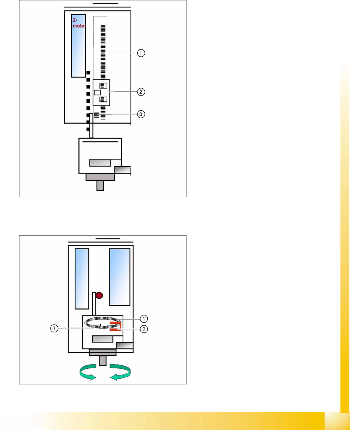
5-8: Z-axis reference run
Legend
1. Incremental scale mounted on moveable part
of the Z-Axis
2. Fixed incremental encoder
3. Zero pulse on the incremental scale (only one
for Z-axis)
Z-axis search for the commutation point of the
linear motors in a special mode. (A 3 phase
motor continues to run at the correct time and
in the correct sequence, when the current is
switched from 1 phase to the next one.)
Then the Z-axis moves upwards to the zero
pulse and loads the zero point correction.
The zero point correction, max. and min. travel
range, are determined when you calibrate the
head height.
5-9: D-axis reference run
Legend
1. Incremental glass scale for D-axis
2. Incremental encoder
3. Zero pulse on incremental glass scale
The D-axis (turning axis) then performs a
reference run.
The D-axis moves to the zero pulse of the D-axis
incremental encoder. The zero point correction is
loaded. The D-axis moves to the reference
position, in accordance with the polarity.
Reference run finished! The gantry reference
run (see Section Gantry) follows.