D-serie level 1 EN.pdf - 第94页
C&P6/12 Placement Heads Placement Procedure Boards – Position Recognition S tuden t Guide Advanced Level 1 SIPLACE D-Series C&P6/12 Placement Heads EN 05/2007 6-14 6.2.3.2 PCB Position Recognition - Centering the…
C&P6/12 Placement Heads
C&P12 in Basic Positon Star 15° Placement Procedure
Student Guide Advanced Level 1 SIPLACE D-Series
EN 05/2007 C&P6/12 Placement Heads
6-13
6.2.2 C&P12 in Basic Positon Star 15°
6.2.3 Boards – Position Recognition
Board position recognition is used to determine the exact position of the board in the machine (conveyor
--> placement area). There should be at least two fiducials on the board. These are then used to
calculated the X/Y position and the rotary angle of the board, in the conveyor system. A maximum of 3
fiducials can be programmed for position recognition. The fiducials should not be on the same line as
one another. In addition to determining the position of the board in the conveyor system, this 3rd fiducial
enables you to determine and correct any displacement within the board (jolted, stretched).
6.2.3.1 Temperature Compensation
In addition to board recognition, SIPLACE D-series machines perform temperature compensation with
the 2nd gantry in the placement area, through PCB position recognition. This compensates another error
source which could affect accuracy.
6-10: C&P12 in basic position star 15°
Star position:
Digits: 15000
Angle 15°
1° is equivalent to 1000 digits
This is the basic C&P12 setting. When the X and
Y axes are in the waiting position, the star axis is
rotated into this basic position (30° at C&P6).
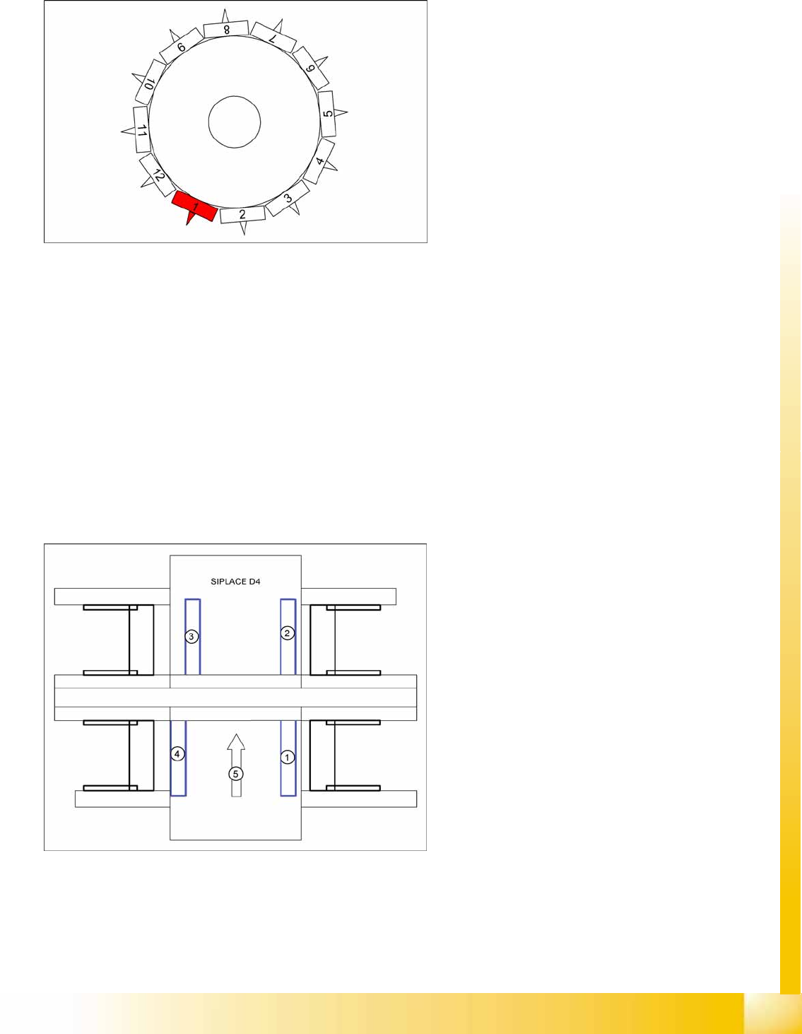
6-11: Board recognition in SIPLACE D4
Legend
1. Gantry 1
2. Gantry 2
3. Gantry 3
4. Gantry 4
5. Transport direction
Gantry 4: position recognition with max. 3
fiducials,
Gantry 2: position recognition with max. 2
fiducials, in PA 2 of D4
Gantries 1 and 3: Temperature compensation
by approaching the fiducials - a position
difference to gantry 4 or 2 is recognized by the
Vision system and is then taken into account and
compensated in the following placement
procedure.
C&P6/12 Placement Heads
Placement Procedure Boards – Position Recognition
Student Guide Advanced Level 1 SIPLACE D-Series
C&P6/12 Placement Heads EN 05/2007
6-14
6.2.3.2 PCB Position Recognition - Centering the PCB Fiducials
6-12: Board recognition run to target position of board
A fiducial is expected at this target position. The
PCB camera moves out of the waiting position to
this fiducial position.
PCB position recognition is performed,
generally before the gantry takes up the 1st
component.
The gantry axes move the PCB camera to the
theoretical fiducial position. The camera
records an image of the 1st fiducial. The Vision
system calculates the center position.
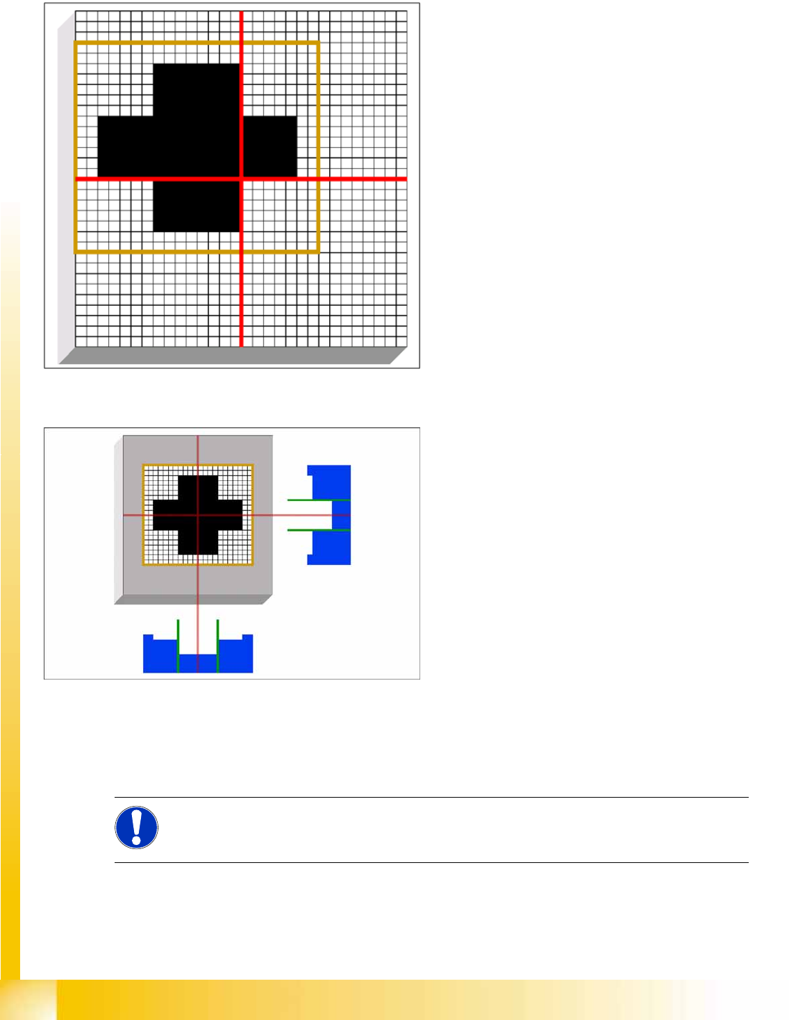
6-13: PCB position recognition - centering the PCB fiducials
The centered fiducial now defines the actual
position of the board.
The camera takes a shot of the 2nd fiducial
and the Vision system calculates the center of
the image.
A second calculation detects any deviation
between the target fiducial position and the
position actually determined.
All PCB fiducials are optically centered using
this method.
This data is then sent to the machine
controller.
The corrected values are then used for the X/
Y and angle positions of the board.
The gantry axes now move the placement
head to the first pickup position.
NOTE: SIPLACE Vision or synthetic fiducials
If synthetic fiducials are used, this does not change the procedure described; although inkspot
recognition is performed after fiducial recognition.
C&P6/12 Placement Heads
Preparing Nozzle 1 - Moving to Pickup Angle (0° or 90°) Placement Procedure
Student Guide Advanced Level 1 SIPLACE D-Series
EN 05/2007 C&P6/12 Placement Heads
6-15
6.2.4 Preparing Nozzle 1 - Moving to Pickup Angle (0° or 90°)
6.2.5 Checking the Nozzle Length for Component Recognition
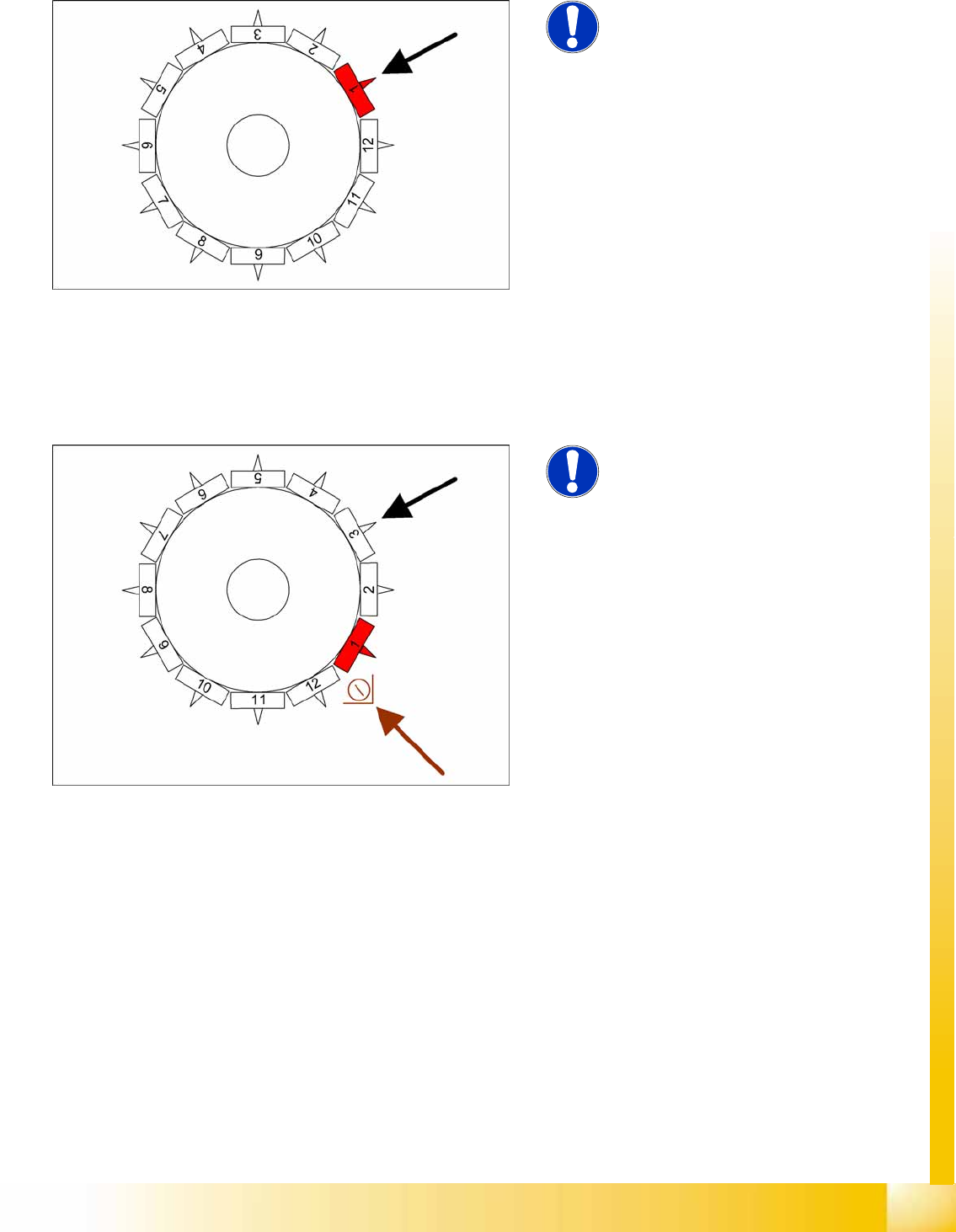
6-14: Rotating nozzle 1 to pickup angle (0° or 90°)
NOTE:
This step is only performed
independently before the very first
pickup cycle.
The star axis rotates to 240°. Nozzle 1 is now
in the DP station.
The DP station swivels in and the DP axis
control system rotates the nozzle to its pickup
angle of 0° or 90° (default pickup angle).
As soon as the nozzle reaches its position, an
end position signal is emitted and the DP
station swivels back.
The other nozzles on the head are then moved
into their pickup angles by further rotation of the
star.
6-15: Checking the nozzle length "Component recognition before placement
by the component sensor"
NOTE:
This step is only performed
independently before the very first
pickup cycle.
Measurement by the component sensor (optional)
at approx. 315°:
The component sensor measures the length of
the empty nozzle*. This measured length
before pickup is compared to the reference
length of the nozzle.
If a difference of -0.15 mm or +0.1 mm is
found, the gantry axes will move the
placement head into the service position for
replacement of the nozzle.
Measurement is performed "on the fly", during
star movement.
* A component which is to use this component
sensor, needs to be picked up for the segment
concerned (component presence check or height
check with component sensor).
All other "conditions" also need to be fulfilled:
Installation/configuration of the option for this
gantry and the appropriate nozzle length.