D-serie level 1 EN.pdf - 第96页
C&P6/12 Placement Heads Placement Procedure Picking Up Component 1 S tuden t Guide Advanced Level 1 SIPLACE D-Series C&P6/12 Placement Heads EN 05/2007 6-16 6.2.6 Picking Up Component 1 6.2.7 Picking up Component…
C&P6/12 Placement Heads
Preparing Nozzle 1 - Moving to Pickup Angle (0° or 90°) Placement Procedure
Student Guide Advanced Level 1 SIPLACE D-Series
EN 05/2007 C&P6/12 Placement Heads
6-15
6.2.4 Preparing Nozzle 1 - Moving to Pickup Angle (0° or 90°)
6.2.5 Checking the Nozzle Length for Component Recognition
6-14: Rotating nozzle 1 to pickup angle (0° or 90°)
NOTE:
This step is only performed
independently before the very first
pickup cycle.
The star axis rotates to 240°. Nozzle 1 is now
in the DP station.
The DP station swivels in and the DP axis
control system rotates the nozzle to its pickup
angle of 0° or 90° (default pickup angle).
As soon as the nozzle reaches its position, an
end position signal is emitted and the DP
station swivels back.
The other nozzles on the head are then moved
into their pickup angles by further rotation of the
star.
6-15: Checking the nozzle length "Component recognition before placement
by the component sensor"
NOTE:
This step is only performed
independently before the very first
pickup cycle.
Measurement by the component sensor (optional)
at approx. 315°:
The component sensor measures the length of
the empty nozzle*. This measured length
before pickup is compared to the reference
length of the nozzle.
If a difference of -0.15 mm or +0.1 mm is
found, the gantry axes will move the
placement head into the service position for
replacement of the nozzle.
Measurement is performed "on the fly", during
star movement.
* A component which is to use this component
sensor, needs to be picked up for the segment
concerned (component presence check or height
check with component sensor).
All other "conditions" also need to be fulfilled:
Installation/configuration of the option for this
gantry and the appropriate nozzle length.
C&P6/12 Placement Heads
Placement Procedure Picking Up Component 1
Student Guide Advanced Level 1 SIPLACE D-Series
C&P6/12 Placement Heads EN 05/2007
6-16
6.2.6 Picking Up Component 1
6.2.7 Picking up Component 6
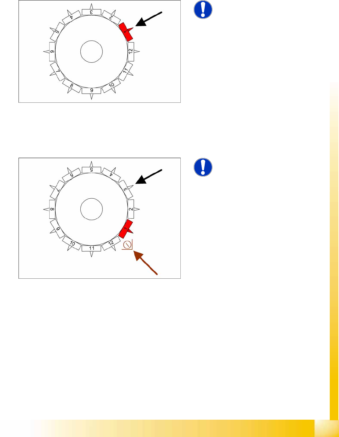
6-16: Picking up component 1
Star position 0°
Vision system: No action
DP station: Rotates nozzle 5 to pickup angle
Pickup/placement station: Picks up
component 1
Component sensor: During the next star cycle,
the nozzle length is measured at segment 3.
The remaining nozzles pick up components as the
star continues to rotate.
NOTE:
The machine learns the pickup heights
for linear feeders and waffle pack trays
during the first 15 pickup runs or so and
may therefore be slightly slower than
calculated by the setup optimization.
(This does not apply to tape feeders)
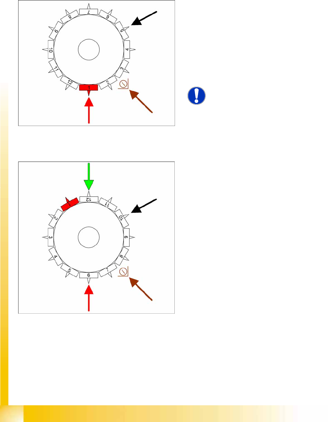
6-17: Picking up component 6
Star position 150°
Vision system: no action
DP station rotation of nozzle 10 to its pickup
angle
Pickup/placement station: Pick up component
6
Component sensor: during the next star step,
the length of nozzle 8 is measured.
C&P6/12 Placement Heads
Picking up Component 7 Placement Procedure
Student Guide Advanced Level 1 SIPLACE D-Series
EN 05/2007 C&P6/12 Placement Heads
6-17
6.2.8 Picking up Component 7
6.2.9 Picking up Component 8
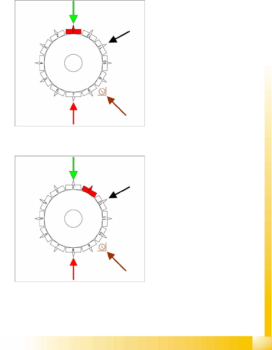
6-18: Picking up component 7
Star position 180°
Vision system: component at segment 1 is
measured
DP station rotation of nozzle 11 to its pickup
angle
Pickup/placement station: Pick up the
component 7
Component sensor: during the next star step,
the length of nozzle 9 is measured.
6-19: Picking up component 8
Star position 210°
Vision system: Component at segment 2 of
this gantry is centered
DP station rotation of nozzle 12 to its pickup
angle
Pickup/placement station: Pick up the
component 8
Component sensor: during the next star step,
the nozzle length is measured at segment 10.