D-serie level 1 EN.pdf - 第151页
SITEST Overview of Settings and Calibr ation Work Calibration S tude nt Guide Advanced Level 1 SIPLACE D-Series EN 05/2007 SITEST 9-7 9.2 Calibration Tools and SITEST Calibration tool – gene ral – Version III not trans…
SITEST
Overview SITEST Overview of Settings and Calibration Work
Student Guide Advanced Level 1 SIPLACE D-Series
SITEST EN 05/2007
9-6
calibrations
from the left to the right
reasons for
calibrations
Zero point corr. star-axis C&P-head
Zero point corr. Z-/ D-axis and basic
force sensor parameter TWIN-head
Calibrate MA-zero point both gantries
of the Placement Area PAx
Calibrate PCB camera
Calibrate RV-head (include
component camera offset and
single measure ment segment offset
I (only for checking offset)
single measure ment segment offset
II (only for checking offset)
Calibrate TWIN Head IC-camera
Calibrate TWIN Head FC-camera
Calibrate coplanarity module (ILD
2200 1 D-version)
Calibrate Feeder area (for D1 WPC
is considered)
Calibrate fixed PCB-corner(s)
Calibrate moveable Conveyor Edges
(rail(s))
Calibrate calibration tool position
Calibrate TWIN-nozzle changer X/Y-
position
Calibrate TWIN-nozzle changer
Nozzle pick up height
Calibrate C&P-nozzle changer X/Y-
position
Calibrate C&P-nozzle changer Pick
up height
Calibrate vacuum TWIN head
Travel area X / Y axis
Execute PCB-Mappings
Execute RV-Mappings
Execute IC-Mappings
Fi
ne ca
lib
ra
ti
on
(if
p
l
acemen
t
accuraccy have to be increased at
Replace / remount PCB-
camera
D/X/
HF
D/X/
HF
D/X/
HF
D1&D3
/X/ HF
w TH
D1&D3
/X/ HF
w TH
D1&D3
/X/ HF
w TH
D/X/
HF
D/X/
HF
D/X/
HF
D1&D3
/X/ HF
w TH
D/X/
HF
D/X/
HF
Replace C&P-head
D/X/
HF
D/X/
HF
D/X/
HF
D/X/
HF
D/X/
HF
D/X/
HF
Remount C&P-head
D/X/
HF
D/X/
HF
D/X/
HF
D/X/
HF
D/X/
HF
Mechanical influence to the
segment guideance
D/X/
HF
D/X/
HF
New Star zero point
correction
D/X/
HF
D/X/
HF
D/X/
HF
compo-nent camera refer.
C&P head
D/X/
HF
D1&D3
/X/ HF
w TH
D1&D3
/X/ HF
w TH
D1&D3
/X/ HF
w TH
Replace / remount
placement star
D/X/
HF
D/X/
HF
D/X/
HF
Replace / remount Star
motor
D/X/
HF
D/X/
HF
D/X/
HF
Replace / remount
Segment(s) TWIN-head
D1&D3
/X/ HF
w TH
D1&D3
/X/ HF
w TH
D1&D3
/X/ HF
w TH
D1&D3
/X/ HF
w TH
D1&D3
/X/ HF
w TH
D1&D3
/X/ HF
w TH
D1&D3
/X/ HF
w TH
Replace / remount TWIN-
head IC-camera
D1&D3
/X/ HF
w TH
D1&D3
/X/ HF
w TH
Replace / remount TWIN-
head FC-camera
D1&D3
/X/ HF
w TH
encoder incremental scale
X/Y
D/X/
HF
D1&D3
/X/ HF
w TH
D1&D3
/X/ HF
w TH
D1&D3
/X/ HF
w TH
D1&D3
/X/ HF
w TH
D/X/
HF
D/X/
HF
Replace / remount LASER
PCB stopper
D/X/
HF
New teaching of fixed PCB-
conveyor side (fixed rail)
D/X/
HF
D/X/
HF
Conveyor mode change
Right <--> Left side fixed
D/X/
HF
D/X/
HF
Use Dual conveyor in Single
conveyor mode **
D/X/
HF
D/X/
HF
Switch Dual conveyor to
dual conveyor mode
D/X/
HF
D/X/
HF
zero point & calib. jig
position
D/X/
HF
D1&D3
/X/ HF
w TH
D1&D3
/X/ HF
w TH
D1&D3
/X/ HF
w TH
D/X/
HF
D/X/
HF
D/X/
HF
D1&D3
/X/ HF
w TH
D/X/
HF
D/X/
HF
Replace / remount
component table
Replace / remount
coplanarity module
D1&D3
/X/ HF
w TH
mechanical influence to the
gantry
D/X/
HF
D1&D3
/X/ HF
w TH
D1&D3
/X/ HF
w TH
D1&D3
/X/ HF
w TH
D/X/
HF
D/X/
HF
D1&
D3/X
/HF
Replace / remount nozzle
changer TWIN-head
D1&D3
/X/ HF
w TH
D1&D3
/X/ HF
w TH
Replace / remount nozzle
changer C&P-head
D/X/
HF
D/X/
HF
Recalibrate machine zero
point (all gantries of a
PA
)
D/X/
HF
D1&D3
/X/ HF
w TH
D1&D3
/X/ HF
w TH
D1&D3
/X/ HF
w TH
D/X/
HF
D1&D3
/X/ HF
w TH
D/X/
HF
Head modularity 6/12 C&P
D/X/
HF
D/X/
HF
D/X/
HF
D/X/
HF
D/X/
HF
D/X/
HF
D/X/
HF
D/X/
HF
XH/
HF
Head modularity
C&P->TWIN
D1&D3
/X/ HF
w TH
D1&D3
/X/ HF
w TH
D1&D3
/X/ HF
w TH
D1&D3
/X/ HF
w TH
D1&D3
/X/ HF
w TH
D1&D3
/X/ HF
w TH
D1&D3
/X/ HF
w TH
D/X/
HF
XH/
HF
Head modularity
TWIN -> C&P
D1&D3
/X/ HF
w TH
D1&D3
/X/ HF
w TH
D1&D3
/X/ HF
w TH
D1&D3
/X/ HF
w TH
D/X/
HF
XH/
HF
Exchange Transport control
unit
D/X/
HF*
First setup (at munich)
D/X/
HF
D1&D3
/X/ HF
wTH
D/X/
HF
D/X/
HF
D/X/
HF
D1&D3
/X/ HF
wTH
D1&D3
/X/ HF
wTH
D1&D3
/X/ HF
wTH
D/X/
HF
D/X/
HF
D/X/
HF
D/X/
HF
D1&D3
/X/ HF
wTH
D1&D3
/X/ HF
wTH
D/X/
HF
D/X/
HF
D1&D3
/X/ HF
wTH
D/X/
HF
D/X/
HF
D/X/
HF
D1&D3
/X/ HF
wTH
D/X/
HF
XH/
HF
Whole calibration of the gantry after head-or head front part disassembling if increased placement accuracy is expected or placement deviation is too high
For the 6 nozzle C&P-head we use 956 nozzles like for the 12 nozzle head.
With 956 nozzles is the lower end of the calibration tool exact in the focus level of the C&P-head component camera. We use 956 for DCA-camera option too.
NOTE !! Calibration of the HS / S / F machines have a different sequence because there is the calibration reference the component camera on the gantry.
Because of construction here, on HF is the reference is the PCB-camera.
* afterTeaching the fixed side 'Right conveyor'
** up to 410 mm Standard to the HS/S/F machines nothing to
calibrate. For larger dimensions on pure HF-

SITEST
Overview of Settings and Calibration Work Calibration
Student Guide Advanced Level 1 SIPLACE D-Series
EN 05/2007 SITEST
9-7
9.2 Calibration
Tools and SITEST
Calibration tool – general –
Version III not transparent is for HF/X/D machines with C&P6/12 and Twin/P&P Head [03010565-01]
(Version II transparent is for S/F/HS machines [00316308-03], calibration nozzle 920)
(Version for SST23 at X machines with C&P20 head [03034148-xx])
Nozzles – general –
Type 956, 517, 518, nozzle for ZPC of D-axis TH [03008862-03]
(C&P20 head: 1235)
Setting gauge for S tables
Board for calibrating the PCB conveyor width
2D coplan - (ILD2200) - calibration tool
SITEST, version 602.xx or higher
DANGER: RISK OF INJURY!
The gantry may move during some of the following procedures.
Therefore, before you begin with any of these procedures make sure that you and everyone else
stay physically clear of the travel range of the gantries.
X Also, sure, that no objects are in the way.
NOTE:
Before you begin with the calibration, you must reference the heads and the gantries.
During calibration, unused gantries will automatically be moved to their parking position.
To completely calibrate the machine, go to
Calibrate machine...
and select the
Calibrating
the entire machine
menu. This provides all the required calibration functions.
SITEST
Calibration Calibration - General Sequence
Student Guide Advanced Level 1 SIPLACE D-Series
SITEST EN 05/2007
9-8
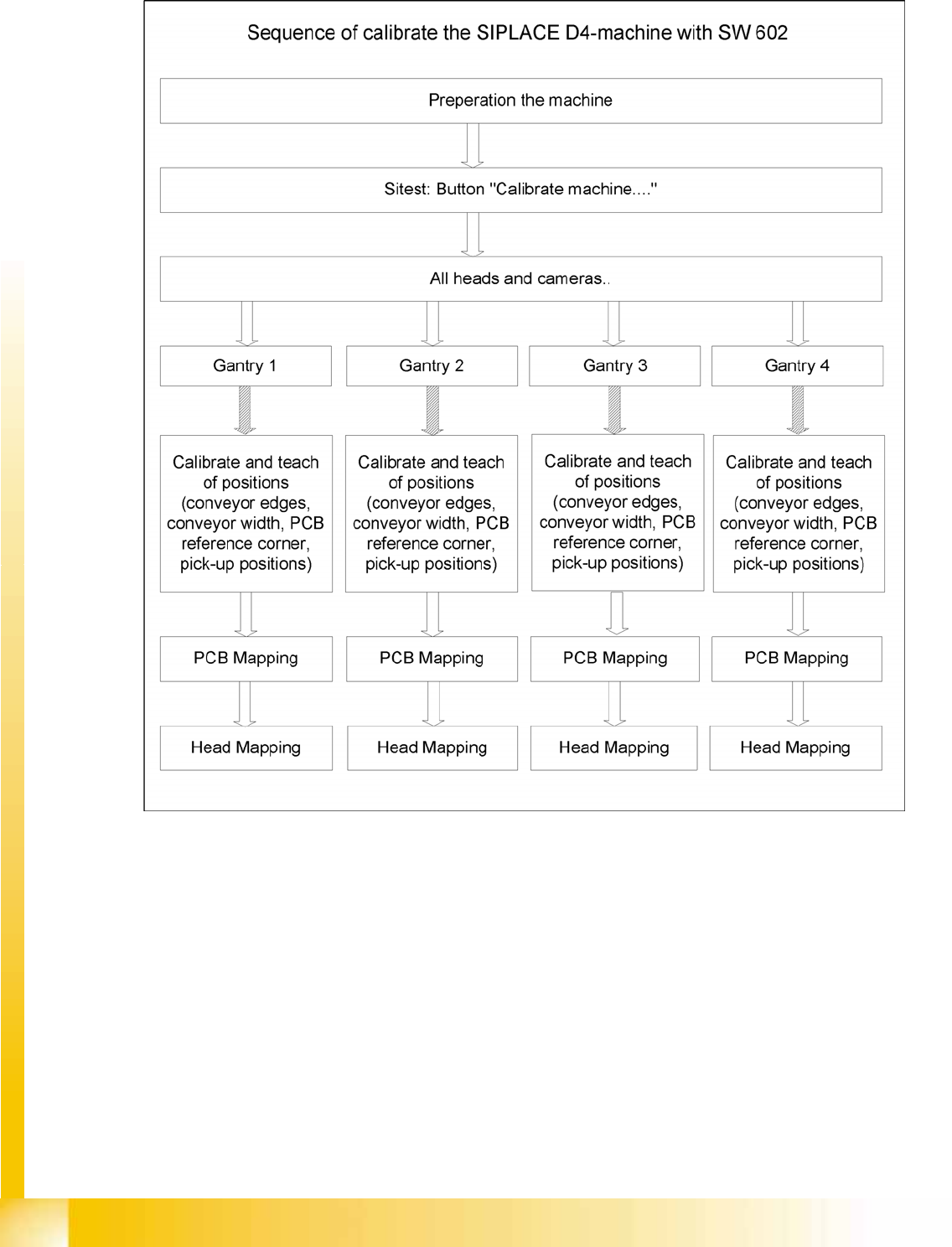
9.2.1 Calibration - General Sequence
9-2: General sequence to calibrate the machine
9.2.2 Requirements for Calibration of Nozzle Changers in the SIPLACE D Machines
X Start SITEST.
X by selecting the menu items
MAIN VIEW
,
Overall reference run
, to start the reference run for all
gantries and heads.
X Configure the nozzle changer and check the component levels.
Precondition for calibrate the nozzle changer
Each magazine in the NC must be configured with a nozzle type.
There should be no nozzle at segment 1 .
Each magazine must at least have a nozzle present and configured (1) in garage 1 .