D-serie level 1 EN.pdf - 第72页
Reference Run Reference Run (D-Series) Axis Reference Run S tuden t Guide Advanced Level 1 SIPLACE D-Series Reference Run EN 05/2007 5-4 5.1.3.2 Gantry Axis Reference Run The first reference run also includ es the commut…
Reference Run
Axis Reference Run Reference Run (D-Series)
Student Guide Advanced Level 1 SIPLACE D-Series
EN 05/2007 Reference Run
5-3
X Star axis reference run
The following steps are performed in sequence:
– In the first reference run, the star axis performs a commutation point search for the 3-phase system
of the drive.
– The star axis positions itself at the axis zero pulse.
– The star axis loads the zero point correction value.
– The star axis positions itself at counter status 0. Segment 1 is now in the star pickup/placement
position.
X Z-axis reference point run
As the Z-axis does not have a zero pulse, the Z-axis end stopper is used for this "zero pulse position".
The zero point correction (ZPC) is determined during each reference run.
– The Z-axis moves again to the top end stopper and then positions itself to the standard value of 5
digits. Subsequently:
– The star axis positions to 6250 digits (6.25°).
– The Z-axis moves down again to the end stopper, transmits the Z-axis position and moves back to
the 5 digit position.
– The star axis positions to 6750 digits (6.75°).
– The Z-axis moves up again to the end stopper, transmits the Z-axis position and moves back to
the 5 digit position.
– The star axis positions to -6250 digits (-6.25°).
– The Z-axis moves down again to the end stopper, transmits the Z-axis position and moves back to
the 5 digit position.
– The star axis positions to -6750 digits (-6.75°).
– The Z-axis moves up again to the end stopper, transmits the Z-axis position and moves back to
the 5 digit position.
X The zero point correction value is calculated from the 4 Z-axis positions, is transmitted to the axis
controller and is used until the machine is switched off.
– The star axis is moved back to the 0 position (segment 1 down).
This automatic zero point correction ensures that the segment ball bearing is in the optimum position
for the circular guide.
X The head axis reference run is now finished.
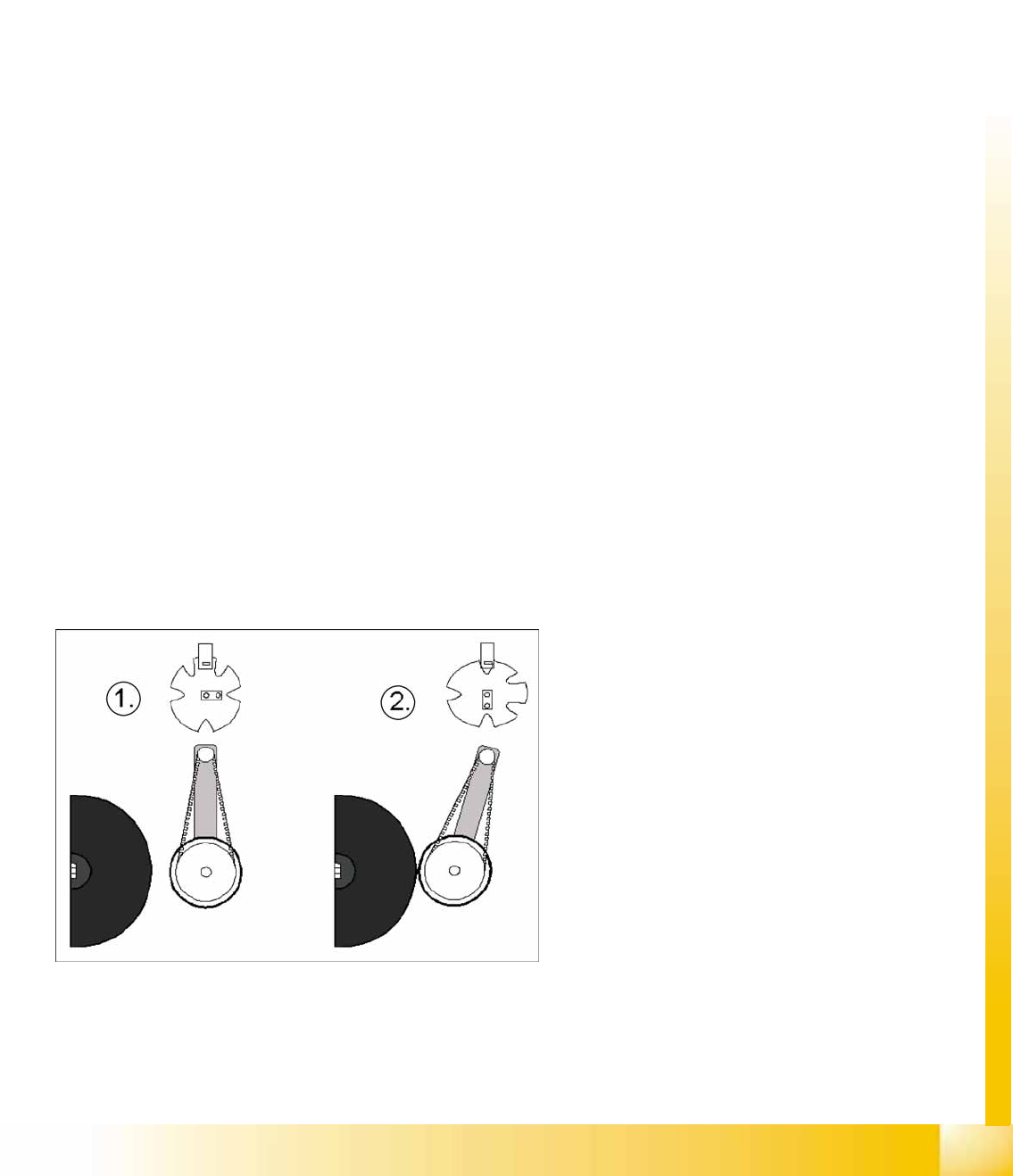
5-3: Positioning the DP axis with the help of the swivel in/out function
Legend
1. Home position of DP drive around 1 mm away
from segment.
2. Engaged position of DP drive at segment
X DP axis reference run
– The DP station is swiveled in by a CAN bus
command (2).
– The axis controller starts from the 0 position
and continues until the incremental encoder
detects a segment zero pulse.
X – The DP station is swiveled out again by a
CAN bus command (1).
Reference Run
Reference Run (D-Series) Axis Reference Run
Student Guide Advanced Level 1 SIPLACE D-Series
Reference Run EN 05/2007
5-4
5.1.3.2 Gantry Axis Reference Run
The first reference run also includes the commutation point search for the 3-phase drive of the gantry
axes.
Sequence:
Initializing the 3-phase drive system and the position measuring system of the gantry axes:
Search for the commutation point of the X/Y axes.
Position at the hardware end stoppers.
The Y gantry axes are stepped to the outer end stoppers.
The target position is predefined. If this is not reached and if no counter pulses can be detected at
the incremental encoder, this means that the axis has reached the hardware end stopper.
Reverse direction of axis movement and search for the zero pulse on the incremental scale.
– Load the X or Y axis zero point correction.
The axis reference run is now finished and the axes can be positioned for placement operation.
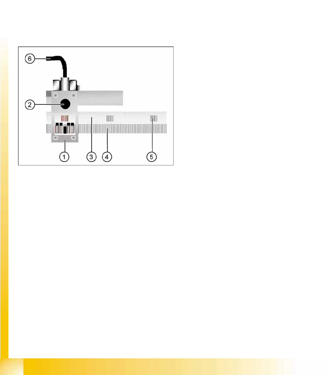
5-4: Diagram of the incremental encoder with scale
Legend
1. Incremental encoder
2. Test plug for track signals (analog)
3. Incremental scale
4. Increments on the scale (1µm resolution)
5. Zero pulse
6. Connection cable to gantry distributor/gantry
head distributor
Reference Run
Vacuum Reference Run Reference Run (D-Series)
Student Guide Advanced Level 1 SIPLACE D-Series
EN 05/2007 Reference Run
5-5
5.1.4 Vacuum Reference Run
5.1.4.1 Nozzle Cleaning, Followed by Vacuum Measurement
The vacuum values "open" and "closed" can only be measured if the nozzles have been cleaned by air
blast to remove any contaminants.
Sequence:
X The gantry axes move the placement head to the reject position.
X The star rotates in an anticlockwise direction to move all segments through the working positions.
X The electromagnetic valve is activated in a cycle for "reject component" and "clean nozzle".
X The vacuum "open" and "closed" placement values are measured for the nozzle types.
Should an error occur, this means that the nozzle opening is too small or that the vacuum duct is
blocked. --> exchange the nozzle.
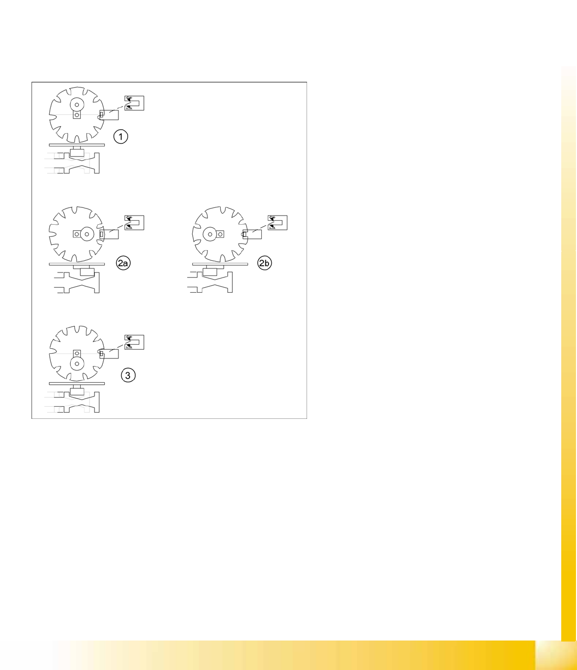
5-5: Switching over the valve positioning drives for pickup/place and reject
positions
Legend
1. Starting position. Give way free for Star axis
movement.
2. 2a: The mode "Valve positioning drive pick/
place" is switched to vacuum for "nozzle
open".
2b: The mode "valve positioning drive pick/
place" is switched to vacuum for "nozzle
closed". Parallel to this (diagram 2b) the "valve
positioning drive reject" is switched back to air
blast (and then back again).
3. Counter position to initial position. Give way
free for Star axis movement.
– The stepping motor of the valve
positioning drive is turned to the home
position. The stepping motor runs and the
light barrier on the cam disk sets the end
signal.
– Because of the special shape of the cam
disk, the stepping motor is able to
recognize the home position (1) or (3).