D-serie level 1 EN.pdf - 第172页
SIPLACE Vision Optical Fiducial Models Fiducial Shapes For PC B Position and Placement Position Recognition S tuden t Guide Advanced Level 1 SIPLACE D-Series SIPLACE Vision EN 05/2007 10-6 Camera image of triangular fidu…
SIPLACE Vision
Fiducial Shapes For PCB Position and Placement Position Recognition Optical Fiducial Models
Student Guide Advanced Level 1 SIPLACE D-Series
EN 05/2007 SIPLACE Vision
10-5
This procedure can also be used for inkspot recognition. Bad quality is recognized if the quality value at
the point found falls below a certain threshold.
10.1.2.2 Patterns as Fiducials
Learning fiducial shapes as patterns with the help of an automated algorithm:
You need to define the search field, the so-called Region Of Interest (ROI).
The reference point of this pattern also needs to be calculated (recommended) or manually
determined (manual definition is less exact). The reference point is the point which the placement
process will later relate to.
The pattern is calculated in order to determine the reference point.
Test the pattern with several other fiducials to establish its reliability (stability of measurement
results).
For reasons of accuracy, the reference points should be determined automatically and then checked
manually.
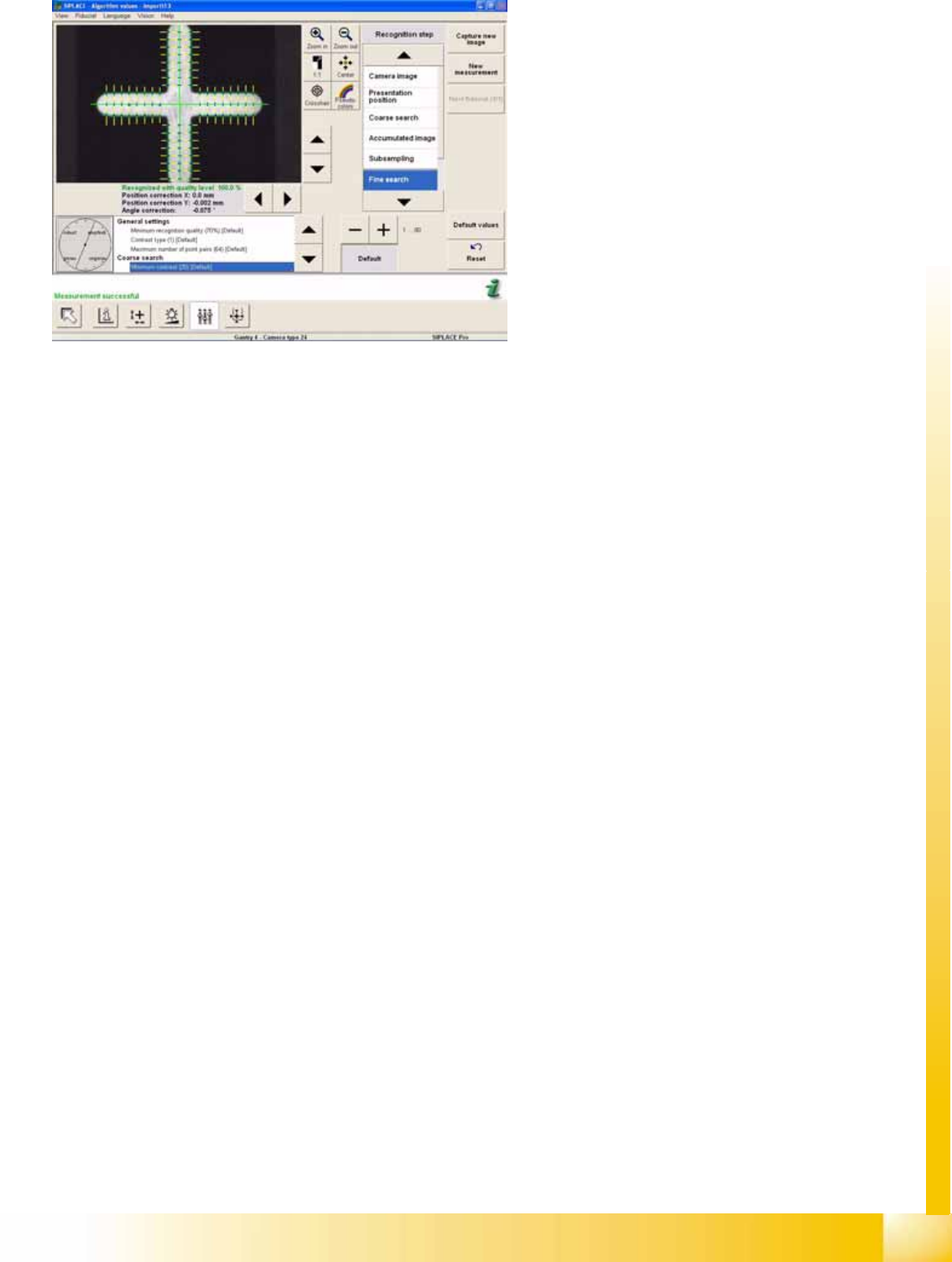
10-1: SC synthetic fiducials, edge position quality 01 0605
The edge position quality for the fine search is set
to 2 as a default.
You can adjust to 1 for very good fiducial edges
and to 4 for very bad ones.A setting of 5 means
that edge deviation checks will no longer be
performed.
For good edge quality 1, the marker is set to
Sensitive against noise or Exact edge position.
For edge quality 5, the marker points to Robust
against edge noiseinaccurate. Greater edge
position deviations are permitted (this more robust
edge position measuring procedure is used for
hot-galvanized fiducials, for example).
SIPLACE Vision
Optical Fiducial Models Fiducial Shapes For PCB Position and Placement Position Recognition
Student Guide Advanced Level 1 SIPLACE D-Series
SIPLACE Vision EN 05/2007
10-6
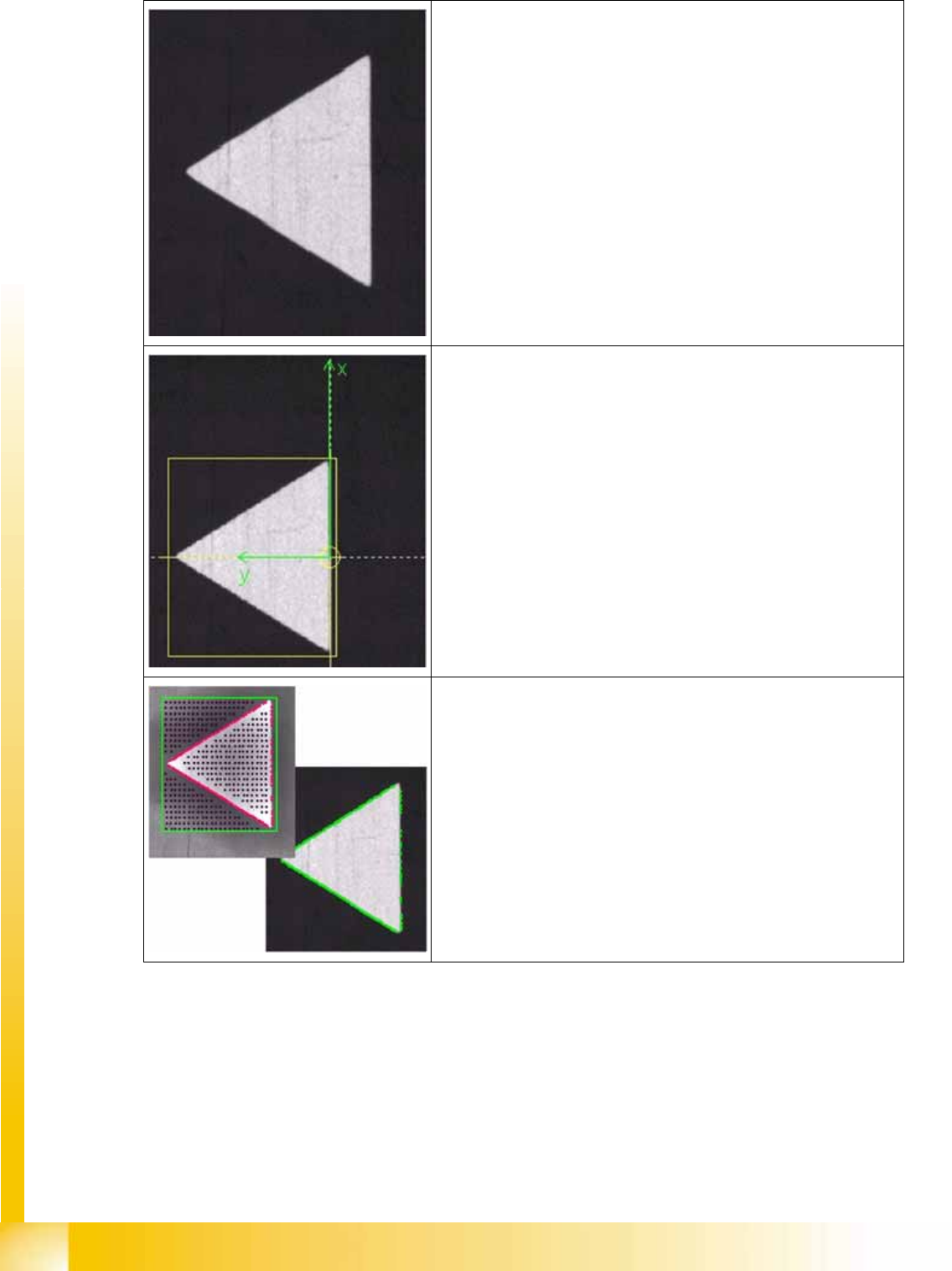
Camera image of triangular fiducial
Determined reference point
The reference point of a fiducial determines the placement positions.
It is therefore important to set it as exactly as possible onto the
positions based on the placement coordinates.
The automatic procedure has selected the point with the greatest
change in brightness, in this case.
Taught pattern:
Starting from the reference point, the system learns the shape of the
pattern and saves this diagram of the outline as the teach image.
(bottom right shows position measurement with taught outline)
SIPLACE Vision
Inkspot Recognition Optical Fiducial Models
Student Guide Advanced Level 1 SIPLACE D-Series
EN 05/2007 SIPLACE Vision
10-7
10.1.3 Inkspot Recognition
There are various programming options for inkspot recognition.
The following measurement results are issued for the structure found:
10.1.3.1 Synthetic Inkspots
Nine different synthetic shapes can be programmed. Similar to teaching, the shape, dimensions and the
optical impression – light or dark – of the positive inkspot need to be taught. If the shape is recognized,
the inkspot will be accepted as a positive inkspot for placement. If the shape is not found in the search
field, the inkspot is understood to be a negative inkspot (no time loss for missing structure) and will not
be placed or, in the case of global inkspots, the local panel inkspots will be approached in the case of
no recognition.
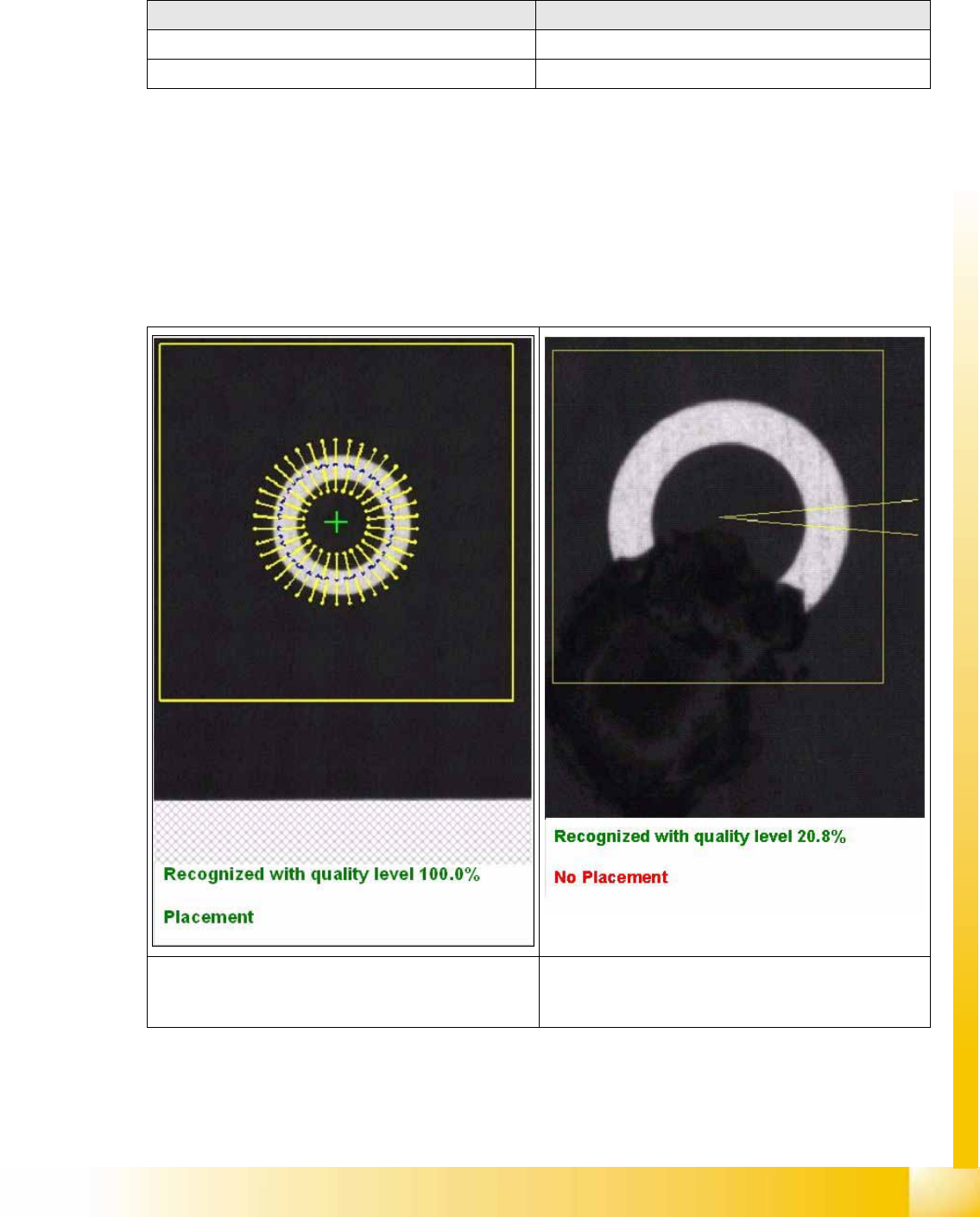
When teaching the fiducial: When centering the fiducial:
=> X/Y position values for approach during teaching => No results shown
=> Placement information:place/omit => Placement information: place/omit
The top diagram shows the fine search procedure for
teaching synthetic inkspots, with the corresponding
results.
This diagram above shows the results for an inkspot
which has been marked as bad.