D-serie level 1 EN.pdf - 第82页
C&P6/12 Placement Heads Overview Camera Modularity at the C&P12 Head S tuden t Guide Advanced Level 1 SIPLACE D-Series C&P6/12 Placement Heads EN 05/2007 6-2 6.1.2 Camera Modularit y at the C&P12 Head For…
C&P6/12 Placement Heads
C&P6/12 Technical Data Overview
Student Guide Advanced Level 1 SIPLACE D-Series
EN 05/2007 C&P6/12 Placement Heads
6-1
6 C&P6/12 Placement Heads
6.1 Overview
6.1.1 C&P6/12 Technical Data
The SIPLACE D4 machines have a C&P12
placement head on each gantry. All other D
machines with the Head Modularity function allow
both C&P12 and C&P6 placement heads to be
fitted.
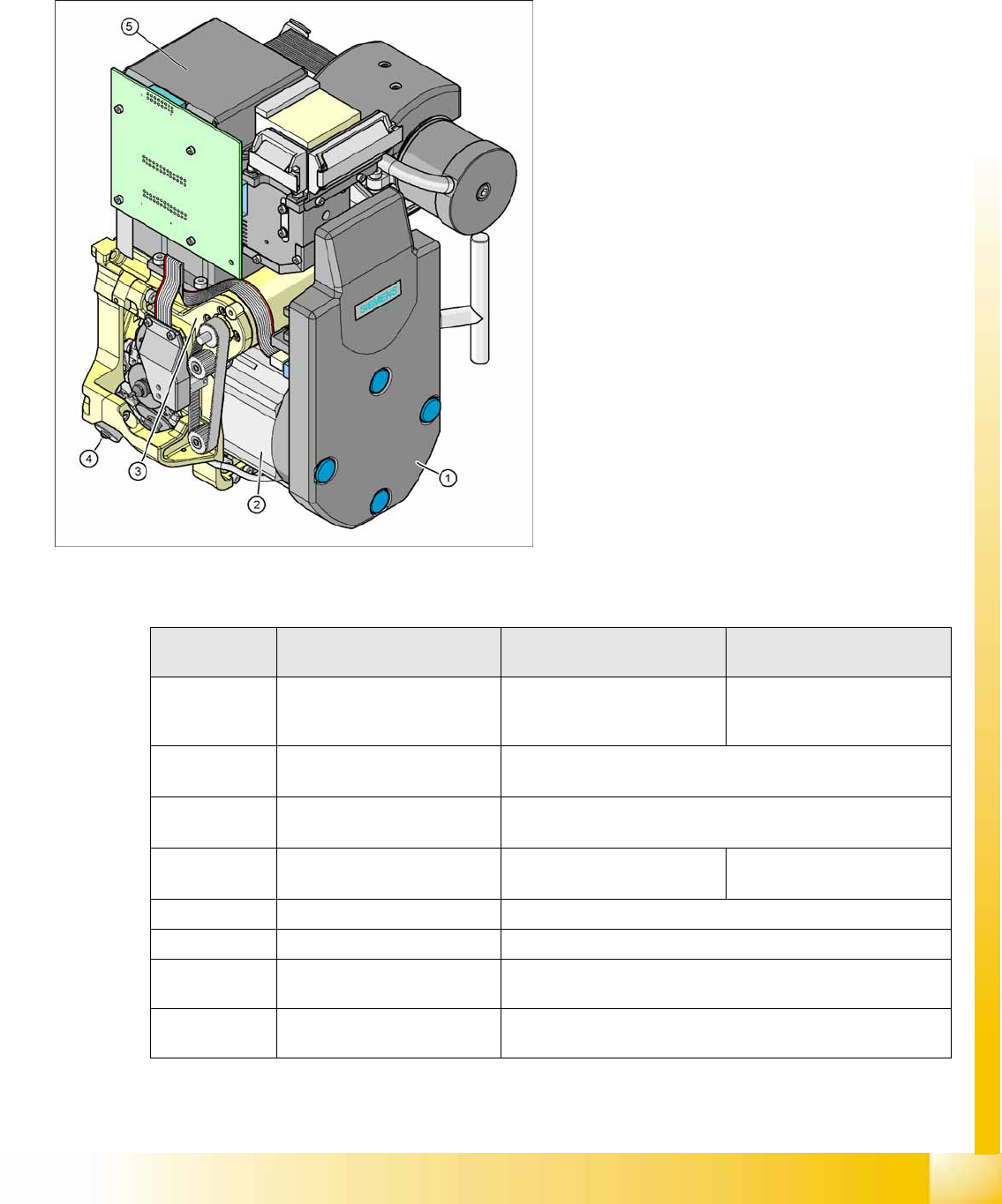
Legend
1. Cover intermediate distributor board, digital
(under the cover)
2. Star drive
3. Z Drive
4. Stepper motor (valve positioning drive)
5. Component camera C&P, type 28 (18x18)
digital or type 29 (27x27) digital, high
resolution component camera 18x18, optional
also for SST29 for 0201 (0.5x0.25 mm) or from
SW 604 also for SST38.
Description 6 segment DLM 3 with SST29 12 segment DLM 3 with
SST28
12 segment DLM 3 with
SST29
Component size 0.6 mm x 0.3 mm (0201) to 27
mm x 27 mm
1mm x 0.5mm (0402)/0.5mm x
0.25mm (0201) up to 18.7 mm
x 18.7 mm
0.6 mm x 0.3 mm (0201)/
0.5 mm x 0.25 mm (0201) to
18.7 mm x 18.7 mm
Component
height
8.5 mm 6,0 mm
Component
weight
5,0 g 2,0 g
Placement
Accuracy
+/- 70 µm for 4 (Sigma) +/- 90 µm for 4 (Sigma) +/- 80 µm for 4 (Sigma)
Angle accuracy +/- 0.3° at 4 (Sigma) +/- 0.7° at 4 (Sigma)
Placement force 2.4 - 5.0 N 2.4 - 5.0 N
Nozzle types 901, 904, 905; 911-919; 920-
925; 931-937 817, 820, 821
901, 904, 905; 911-919; 920-925; 931-937
Nozzle Changer set up for each magazine or
set up for each garage
set up for each magazine or set up for each garage
C&P6/12 Placement Heads
Overview Camera Modularity at the C&P12 Head
Student Guide Advanced Level 1 SIPLACE D-Series
C&P6/12 Placement Heads EN 05/2007
6-2
6.1.2 Camera Modularity at the C&P12 Head
For further values, refer to the official camera description.
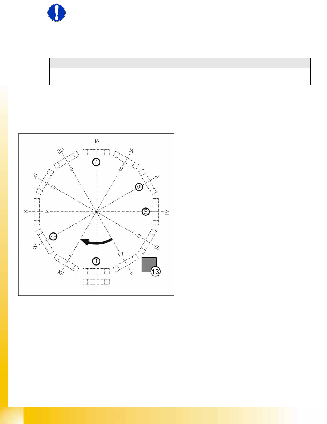
6.1.3 Position and Function of the Individual Star Stations
Star station 1
Pickup cycle
The nozzle is lowered onto the component. After the vacuum circuit to the nozzle has been opened
by the valve positioning unit, the nozzle picks up the component (suction) and removes it from the
feeder module.
Placement cycle
The nozzle, together with the component, is lowered onto the PCB that has been moved into place.
The valve positioning unit closes the vacuum duct to the nozzle. A brief air blast separates the
component from the nozzle. The component is placed down on the board.
NOTE:
The standard camera on the C&P12 is the 28.sst, although the component camera 29.sst, with
a higher resolution (for small 0201 components), can be installed as an option (the same
maximum component dimensions apply in this case).
Smaller maximum component dimensions apply when using the SST38 camera option.
For further settings and data for the C&P12 head, see the specifications for the relevant option.
Description 12 segment standard SST29 12 segment with SST38
Component size: Flip Chip/Bare
Die
0.6 mm x 0.3 mm (0201) 0.2 mm x 0.1 mm (01005) placement
Legend
I-XII segment numbering
1. Star station 1: Pick up component and place
2. Star station 2: No function
3. Star station 3: Reject component
4. Star station 4: No function
5. Star station 5: No function
6. Star station 6: No function
7. Star station 7: Optical centering of component
8. Star station 8: No function
9. Star station 9: Rotate component
10. Star station 10: Position for removal and
insertion of sleeves
11. Star station 11: No function
12. Star station 12: No function
13. Component sensor (optional, between star
station 11 and 12)
C&P6/12 Placement Heads
Overview of C&P6/12 Head Parts Overview
Student Guide Advanced Level 1 SIPLACE D-Series
EN 05/2007 C&P6/12 Placement Heads
6-3
Star station 3
Reject cycle
Once the gantry has reached the X/Y reject coordinates, the valve positioning unit closes the vacuum
duct to the nozzle. Faulty components are separated from the nozzle with a short air blast of
compressed air and are discarded.
Star station 7
The component is optically centered.
Star station 9
Pickup cycle
The nozzle is rotated into the pickup position.
Placement cycle
The component is rotated into the placement position.
Star station 10
Position for removal and insertion of sleeves for maintenance
Between star station 11&12
Option for C&P12: the presence or height of the component is checked before placement.
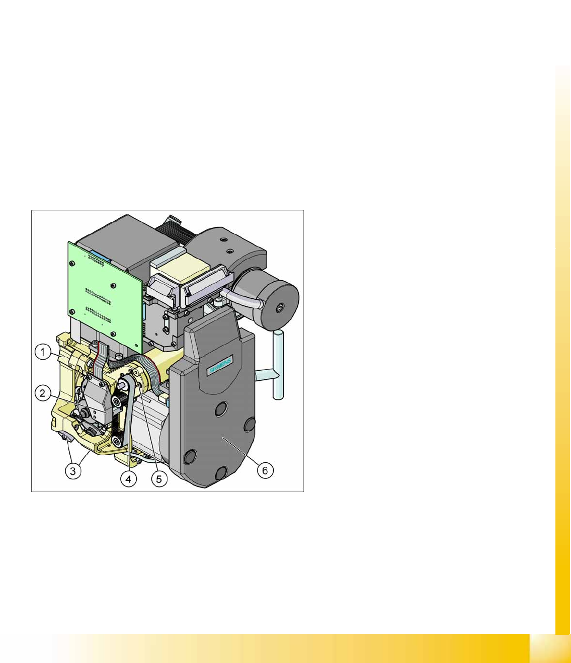
6.1.4 Overview of C&P6/12 Head Parts
6-1: C&P12 head
Legend - overview of parts 1
1. Collect&Place head 12 (DLM3)
[03041228-xx] (shown)
Collect&Place head 6 (DLM3)
[03048341-xx] (not for D4)
2. Light barrier "Z Axis Up " (behind the cover)
[00347297-xx]
3. Valve positioning drive, placement circuit
[00368076-xx]
Valve positioning drive, reject circuit
[00368074-xx]
4. Z-axis toothed belt
[00334936-xx]
5. Z-axis drive / DLM2
[03038908-xx]
6. Intermediate distributor, digital (behind the
cover)
[00330648-xx]