1OM-1003-007.pdf - 第113页
1.1 Inspections before Automatic Operation 1.1.1 Confirmation of Power Supply and Air Pressure (1) Confirmation of Power Supply Confirm that the local main breaker (the power supply to the ma- chine) is "ON". •…
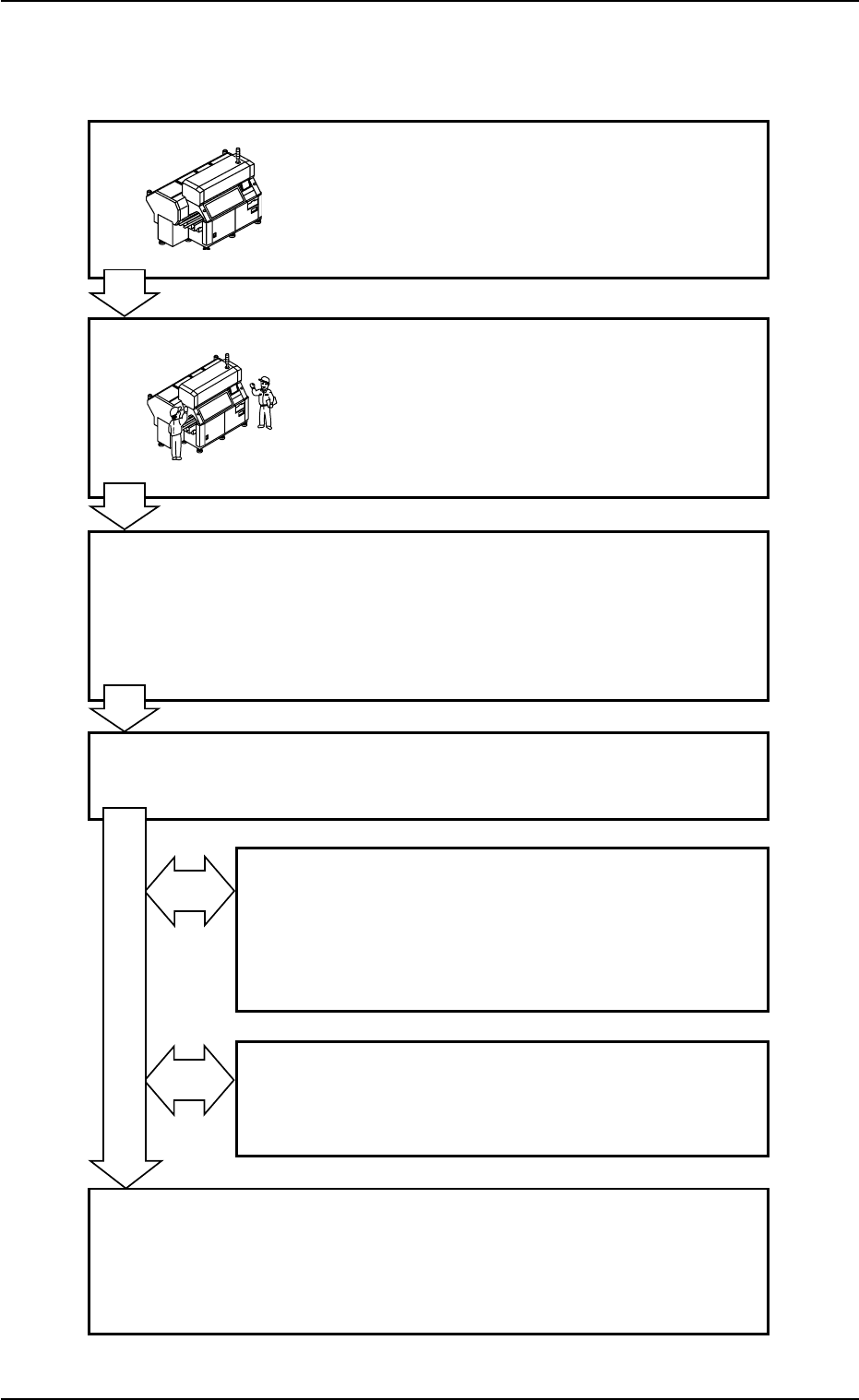
1. Normal Automatic Operation
Flow of Automatic Operation
Program Change Operation
Refer to "Volume 2: Operation (Supervisor)" for
details.
Inspections before Automatic Operation
1.1.1 Confirmation of Power Supply and Air
Pressure
1.1.2 Confirmation of Front Safety Door and
Feeder Carriage Sections
Preparation before Automatic Operation
1.2.1 Power ON Operation
1.2.2 "AUTO OPN." Window and Zeroing of
Each Device
1.2.3 Preparation for Components and P.C.B.’s
Start of Automatic Operation
1.3 Start of Automatic Operation
Temporary Stop and Restart of Automatic Operation
1.4.1 Replenishment of Components and P.C.B.’s
1.4.2 [STOP] and [ON] (entitled "STOP") Buttons
1.4.3 Stop Operation by Selection of "Auto Stop
Mode"
Interruption of Automatic Operation
1.5.1 Interruption of Automatic Operation with
[CANCEL] Button
End of Automatic Operation
1.6.1 Stop of Automatic Operation
1.7.1 Shut-Down Procedure
1.7.2 Locking the Power Breaker with the Padlock
1. Normal Automatic Operation
Fig. 1C2
0412-002 3-1 AIL01EOPP
Fig. 1C1
1.1 Inspections before Automatic Operation
1.1.1 Confirmation of Power Supply and Air Pressure
(1) Confirmation of Power Supply
Confirm that the local main breaker (the power supply to the ma-
chine) is "ON".
• Power Supply : 200±20 V AC, 3-Phase
• Apparent Power : TCM-X110J : Approx. 14 kVA
TCM-X300S : Approx. 14 kVA
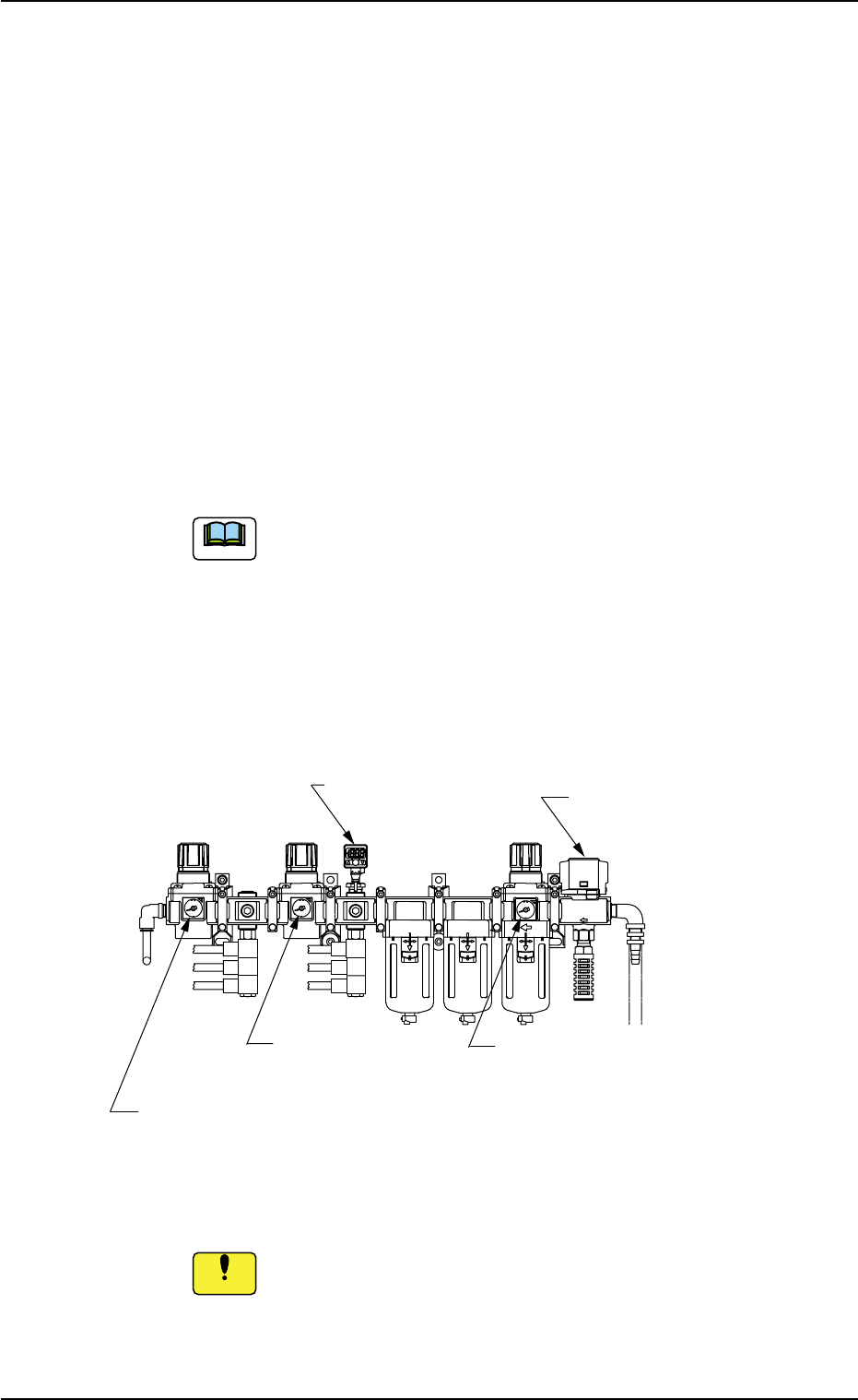
(2) Confirmation of Air Pressure
Confirm that the air pressure is set to the value specified below.
• Main Pressure : 0.5 MPa (5.1 kgf/cm
2
)
The above represents the pressure specified while the
machine is in the "STOP" mode.
Min. 0.4 MPa (4.1 kgf/cm
2
) is required while the machine
is running.
• Sub Pressure : 0.29 MPa (3 kgf/cm
2
)
• Air Blowing Pressure : 0.05 MPa (0.5 kgf/cm
2
) to
0.08 MPa (0.8 kgf/cm
2
)
Fig. 1C3 Air Regulator
Do not change the set air pressure. Otherwise, the pneumatic
devices will not work normally.
1.1 Inspections before Automatic Operation
0412-004 3-2 AIL01EOPP
Air Blowing Pressure
0.05 MPa (0.5 kgf/cm
2
)
to 0.08 MPa (0.8 kgf/cm
2
)
Sub Pressure
0.29 MPa (3 kgf/cm
2
)
Pressure Switch
Main Pressure
0.5 MPa (5.1 kgf/cm
2
)
Main Valve
(Identified as "SUP.")
Note
Notice
(a) When the air pressure is not set correctly, adjust it to meet
the specified range.
(b) The pressure switch is correctly set. Be sure not to ad-
just it.
Ref.: 0.40 MPa for P1 and 0.35 MPa for P2
(c) Use of Dry and Clean Air
Be sure to use dry and clean air. If moisture, oil, dust, etc.,
enter a pneumatic device (air cylinder, etc., used in this
machine), it will result in a breakdown of the machine.
Dry and Clean Air
Moisture: Dew Point -17°C or lower (Atmospheric Pres-
sure)
Oil : 0.1 mg/m
3
(ANR) or less
Dust : Solid Material 0.01 µm or less
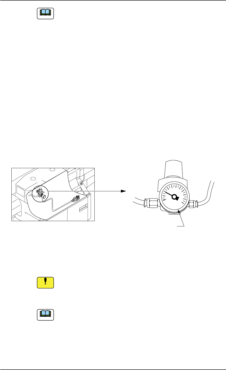
(3) Confirmation of Z-Clamp Pressure
Confirm that the Z-clamp pressure is set to "0.2 MPa (2.0 kgf/cm
2
)".
Fig. 1C4 Air Regulator for Z Clamp
Do not adjust the pressure of the Z clamp.
• If the set air pressure is changed, the Z-clamp function may not
work normally.
When the pressure of the Z clamp is not set correctly and
the Z-clamp function does not work normally, contact our ser-
vice station or sales agency.
1.1 Inspections before Automatic Operation
0511-003 3-3 AIL01EOPP
Note
MPa
SMC
1
0.8
0.6
0.4
0.2
0
Pressure of Z Clamp
0.2 MPa (2.0 kgf/cm
2
)
The pressure of the Z clamp can be
checked from the top after the front
safety door is opened.
Do not detach the front cover.
Note
Notice