1OM-1003-007.pdf - 第87页
2.3.6 Rear Service Panel Fig. 1A19 *1 Selector Switch This switch is used to select either the operation panel of the main machine or the secondary operation panel for maintenance. Keep the selector switch "OFF"…
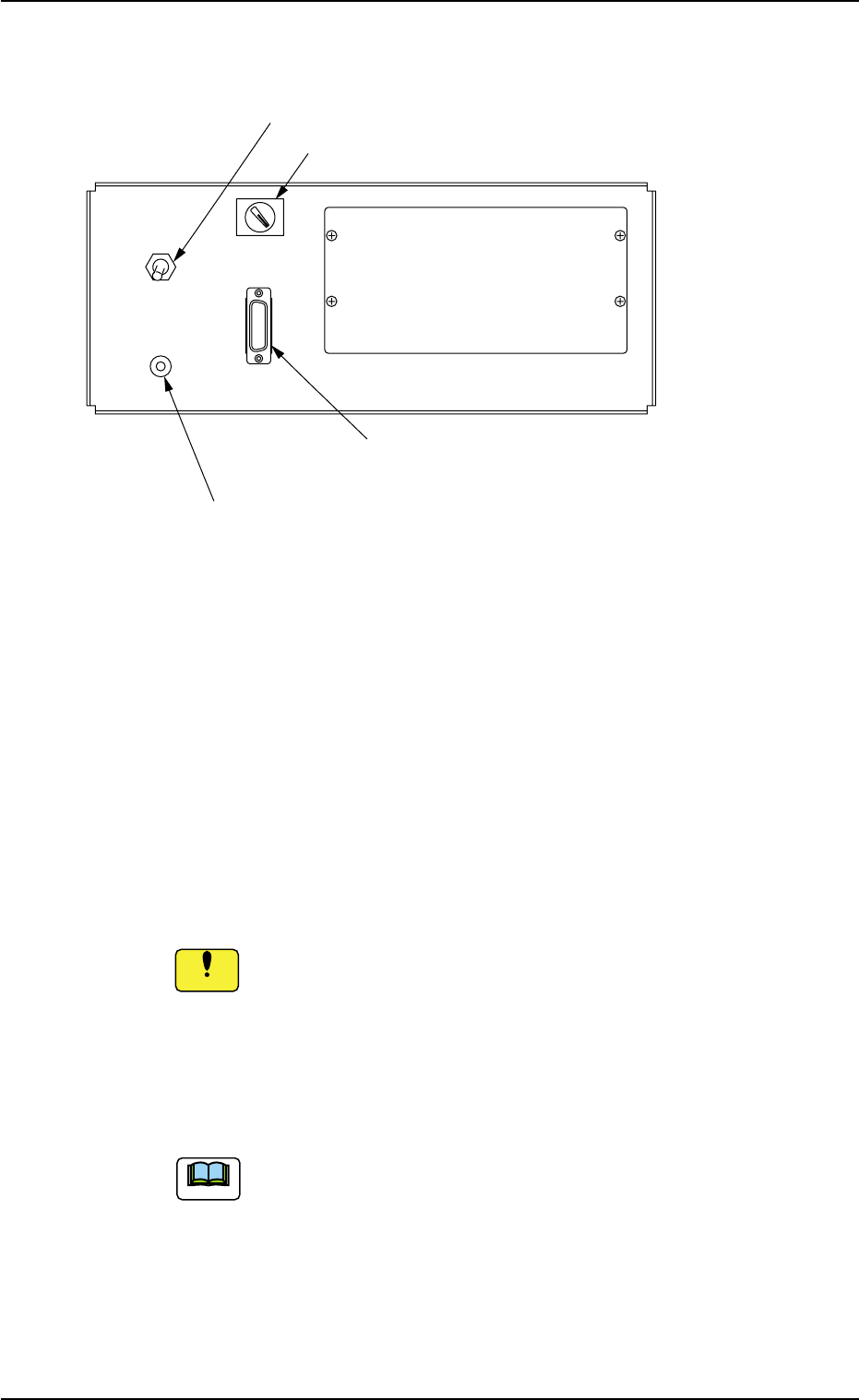
2.3.5 Front Service Panel
Fig. 1A18
*1 Working Lamp Switch
This switch is used to turn on or off the working spot lamp.
*2 Ground Terminal for Wrist Band
This terminal is used to clear a ground through the wrist band.
*3 Selector Switch
This switch is used to select either the operation panel "OFF" of the
main machine or the secondary operation panel "ON" for mainte-
nance.
Keep the selector switch "OFF" during automatic operation.
When the switch is turned "ON", the power will be cut off.
*4 Connector for Secondary Operation Panel
This connector is used to connect the secondary operation panel
for maintenance.
This connector is provided only for a service personnel.
2.3 Operational Measures
ON OFF
LIGHT
OPE-TAB
*3 Selector Switch
*1 Working Lamp Switch
*2 Ground Terminal
for Wrist Band
*4 Connector for Secondary
Operation Panel
0412-002 1-23 AIL01EOPP
Note
Notice
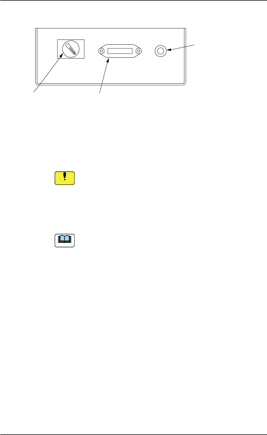
2.3.6 Rear Service Panel
Fig. 1A19
*1 Selector Switch
This switch is used to select either the operation panel of the main
machine or the secondary operation panel for maintenance.
Keep the selector switch "OFF" during automatic operation.
When the switch is turned "ON", the power will be cut off.
*2 Connector for Secondary Operation Panel
This connector is used to connect the secondary operation panel
for maintenance.
This connector is provided only for a service personnel.
*3 Ground Terminal for Wrist Band
The wrist band must be connected to this terminal for grounding.
2.3 Operational Measures
ON OFF OPE-TAB
*1 Selector Switch
*2 Connector for Secondary
Operation Panel
*3 Ground Terminal
*3 for Wrist Band
0412-002 1-24 AIL01EOPP
Note
Notice
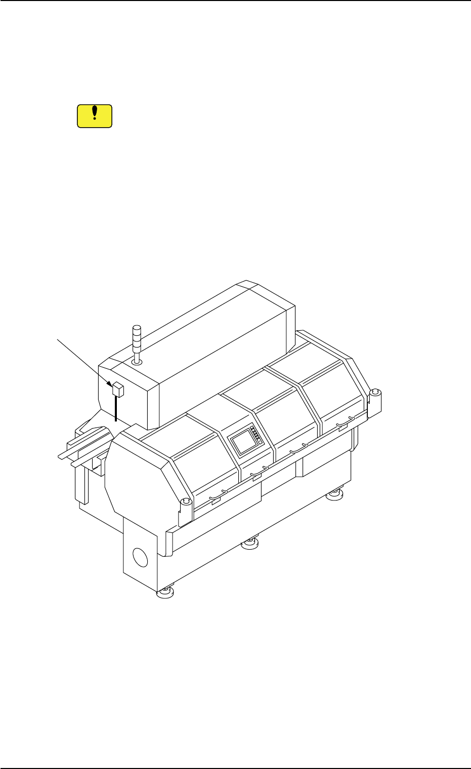
2.3.7 Ethernet LAN
Data can be exchanged between the network terminal (option) and the
machine in the Ethernet LAN system.
• Do not exchange data through Ethernet cabling (Local
Area Network) between the system and a computer that
is not provided with any viral strategies.
Otherwise, viruses might enter the network, causing the ma-
chine to malfunction.
• Isolate the system without using Ethernet cabling (Lo-
cal Area Network) except for the specified functional
operations.
Otherwise, the machine will break down.
Fig. 1A20
2.3 Operational Measures
Ethernet LAN
0412-002 1-25 AIL01EOPP
Notice