1OM-1003-007.pdf - 第92页
2.4.4 X/Y T able Section Fig. 1A24 The X/Y table section is provided with a mechanism that holds a P .C.B. (sent from the conveyor on the input side) firmly on the X/Y table. The firmly-held P .C.B. moves and stops under…
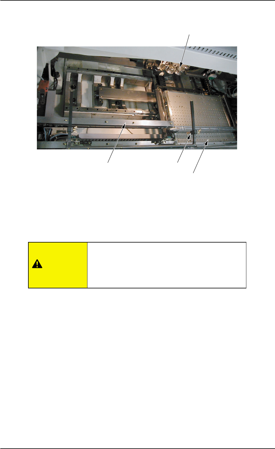
2.4.3 P.C.B. Transfer Section
Fig. 1A23
The P.C.B. transfer section is equipped with a feed claw that pushes
and transfers the P.C.B. (the P.C.B. received from the input machine by
the L conveyor when the flow direction is "L Æ R") onto the X/Y table.
It is very dangerous for a person or a thing to come in
contact with the feed claw.
Special care is required during working with the front
safety door being open.
2.4 Main Units
0412-002 1-28 AIL01EOPP
Rotary Turret
L Conveyor
X/Y Table
P.C.B. Transfer Claw
CAUTION
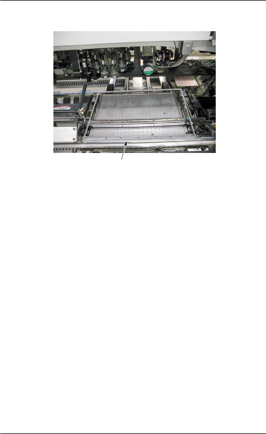
2.4.4 X/Y Table Section
Fig. 1A24
The X/Y table section is provided with a mechanism that holds a P.C.B.
(sent from the conveyor on the input side) firmly on the X/Y table.
The firmly-held P.C.B. moves and stops under the placement heads
together with the X/Y table according to the pattern program data. Com-
ponents are placed on the P.C.B. there.
It is required to adjust the positioning pin, the positioning lever, and the
movable chute to firmly hold the P.C.B. (P.C.B. positioning).
2.4 Main Units
X/Y Table
0305-001 1-29 AIL01EOPP
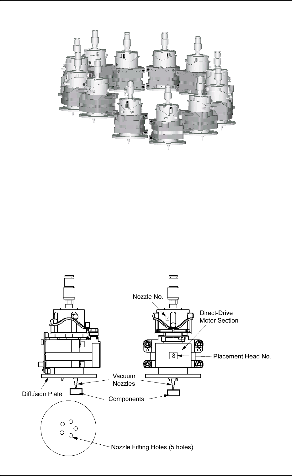
2.4.5 Placement Head Section
Fig. 1A25
The machine is provided with a rotary turret that has several heads.
Each head is rotated by a direct-drive motor and several vacuum nozzles
can be attached to one head. The attached vacuum nozzles are used to
pick up components and place them on a P.C.B.
The turret has 12 placement heads.
Each head has 5 fitting holes for nozzles. Up to 5 types of vacuum
nozzles can be attached to each head.
Fig. 1A26
2.4 Main Units
0305-001 1-30 AIL01EOPP