1OM-1003-007.pdf - 第94页
2.4.6 Component Recognition Section Fig. 1A27 The machine is provided with a mechanism that inspects (recognizes) the components picked up by vacuum nozzles, using two component recognition cameras and three light source…
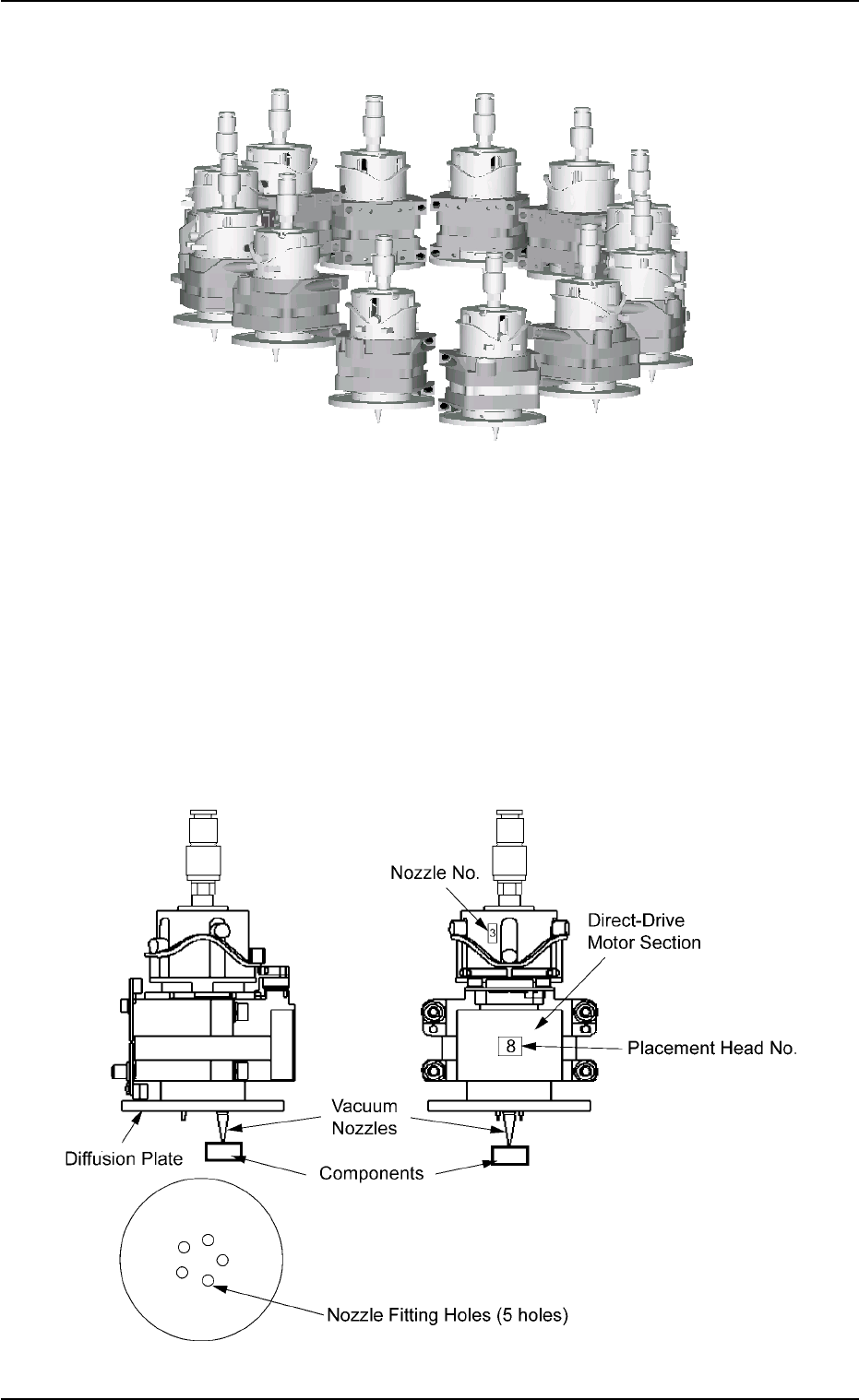
2.4.5 Placement Head Section
Fig. 1A25
The machine is provided with a rotary turret that has several heads.
Each head is rotated by a direct-drive motor and several vacuum nozzles
can be attached to one head. The attached vacuum nozzles are used to
pick up components and place them on a P.C.B.
The turret has 12 placement heads.
Each head has 5 fitting holes for nozzles. Up to 5 types of vacuum
nozzles can be attached to each head.
Fig. 1A26
2.4 Main Units
0305-001 1-30 AIL01EOPP
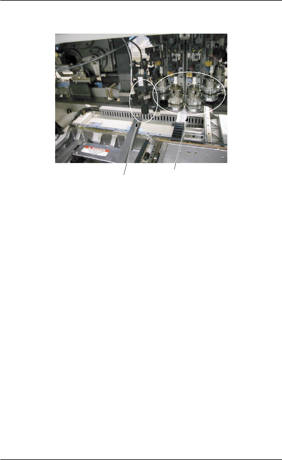
2.4.6 Component Recognition Section
Fig. 1A27
The machine is provided with a mechanism that inspects (recognizes)
the components picked up by vacuum nozzles, using two component
recognition cameras and three light sources.
The following three operations are performed in the compo-
nent recognition system.
• Component Detection
• Component Inspection based on Component Library Data
• Measurement of Positional and Angular Deviations
2.4 Main Units
0309-002 1-31 AIL01EOPP
Component Recognition Scope Section
Note
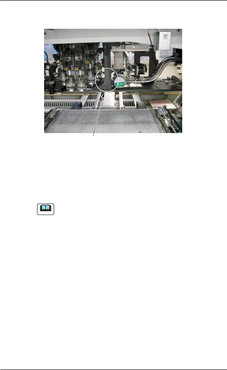
2.4.7 P.E.C. Recognition Section
Fig. 1A28
The P.E.C. recognition camera is used to detect the fiducial marks on a
P.C.B. and the amount of the positional deviation from the fiducial mark
coordinate data is calculated to automatically correct the position of a
placed component.
2.4 Main Units
0305-001 1-32 AIL01EOPP
P.E.C. Recognition Camera
Rotary Turret