1OM-1003-007.pdf - 第118页
This machine is provided with a password function which pre- vents various types of data groups from being deleted by mis- take and keeps unauthorized user (third party) from operating the machine. The following three ki…
(4) Hold down the [POWER ON] button on the operation panel for one
second or more.
The lamp of the [POWER ON] button illuminates in yellowish green
and the self-diagnostics function starts.
Fig. 1C8
It takes 2 to 3 minutes until the self-diagnostics operation is
completed. Please wait for a while.
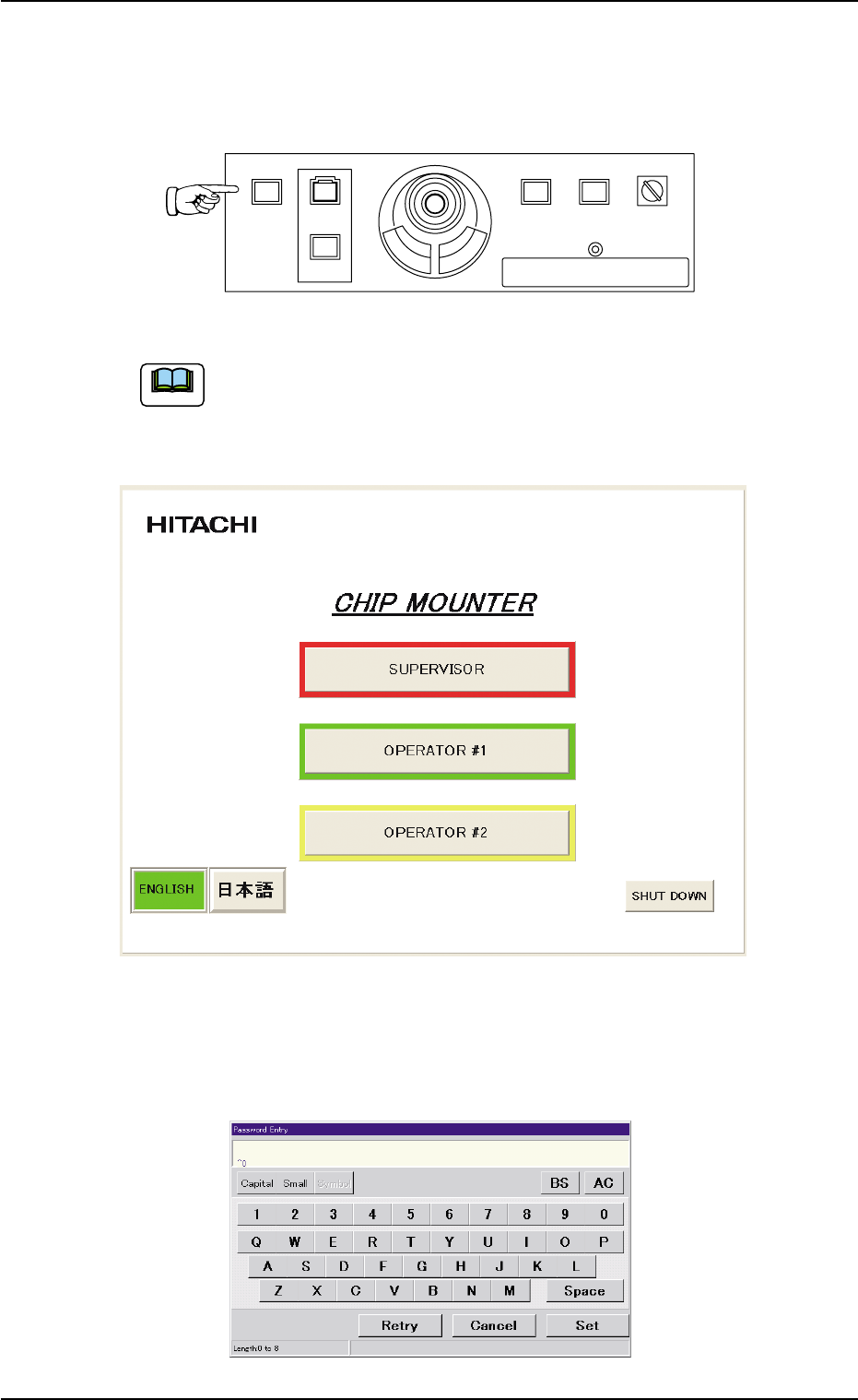
When the self-diagnostics operation is completed, "Login Type Selec-
tion" window appears on the touch screen.
Fig. 1C9
(5) Press the [SUPERVISOR], the [OPERATOR #1], or the [OPERA-
TOR #2] button according to the given authority. When a password
is set, the "Password Entry" window opens.
Fig. 1C10
POWER ON
STOP
START
ENABLE
RUN SETUP
OPERATION
LOCK
PNL CHANGE
1.2 Preparation before Automatic Operation
Note
0511-002 3-6 AIL01EOPP
This machine is provided with a password function which pre-
vents various types of data groups from being deleted by mis-
take and keeps unauthorized user (third party) from operating
the machine.
The following three kinds of passwords are available and each
gives individually approved user’s access to the computer sys-
tem of the machine.
Refer to "Password Setting" in "Section 5 Menus for System
Setting" of "Volume 3: Programming and Machine Data" for
details.
[SUPERVISOR] : Access can be gained by only the person
identified as "Supervisor".
[OPERATOR #1] : Access can be gained by only the person
identified as "Operator #1". For example, the
person identified as "Operator #1" is given
a permission to all machine operations in-
cluding data editing.
[OPERATOR #2] : Access can be gained by only the person
identified as "Operator #2". For example, the
person identified as "Operator #2" is limited
to only the operations related to the auto-
matic operation.
1.2.2 "AUTO OPN." Window and Zeroing of Each Device
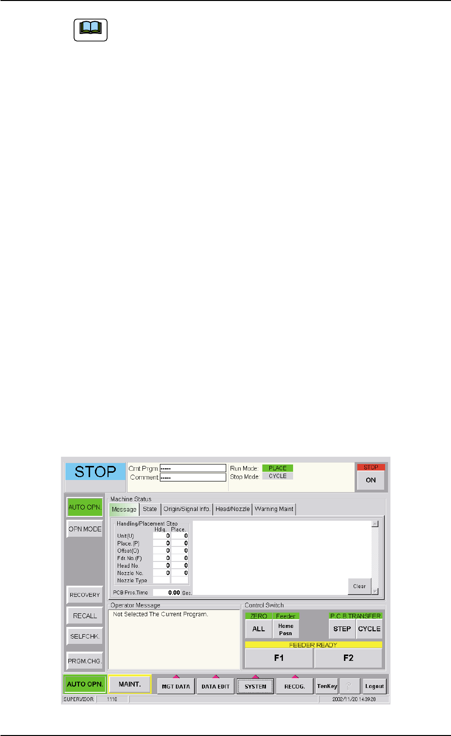
(1) Enter the password and press the [OK] button.
The main menu bar appears and the "AUTO OPN." window opens
on the operation screen.
Fig. 1C11
1.2 Preparation before Automatic Operation
Note
0305-001 3-7 AIL01EOPP
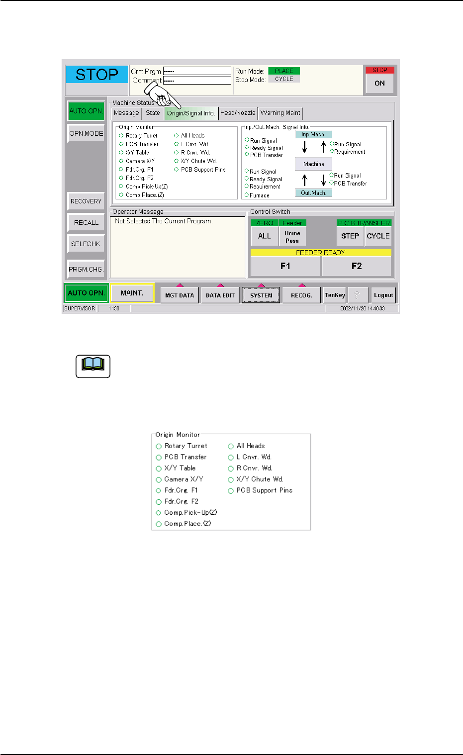
(2) Press the [Origin/Signal Info.] tab to open the "Origin/Signal Info."
tab sheet and perform the zeroing operations.
Fig. 1C12
When the origin marks "
•
" are not displayed for all devices
except "L Cnvr. Wd.", "R Cnvr. Wd.", "X/Y Chute Wd.", and
"PCB Support Pins" in the "Origin Monitor" group box of the
"Origin/Signal Info." tab sheet, the automatic operation cannot
be started.
Fig. 1C13
When the origin mark "
•
" does not appear before any device other than
"L Cnvr. Wd.", "R Cnvr. Wd.", "X/Y Chute Wd.", and "PCB Support Pins",
follow the steps below to perform the zeroing operation.
Operation Procedure
1. Confirm that the machine is set in the "STOP" mode.
2. Confirm that the front safety door, the feeder work area safety doors,
and the feeder carriage covers are closed.
3. When the [ENABLE] button on the operation panel is pressed in
two seconds after the [ALL] button (entitled "ZERO"), all devices
except "L Cnvr. Wd.", "R Cnvr. Wd.", "X/Y Chute Wd.", and "PCB
Support Pins" are zeroed.
1.2 Preparation before Automatic Operation
Note
0305-001 3-8 AIL01EOPP