1OM-1003-007.pdf - 第77页
*3 [STOP] Button • This button is used to stop the automatic operation. • When this button is pressed during X/Y table test, the test operation stops. • When this button is pressed during zeroing operation, the zeroing o…
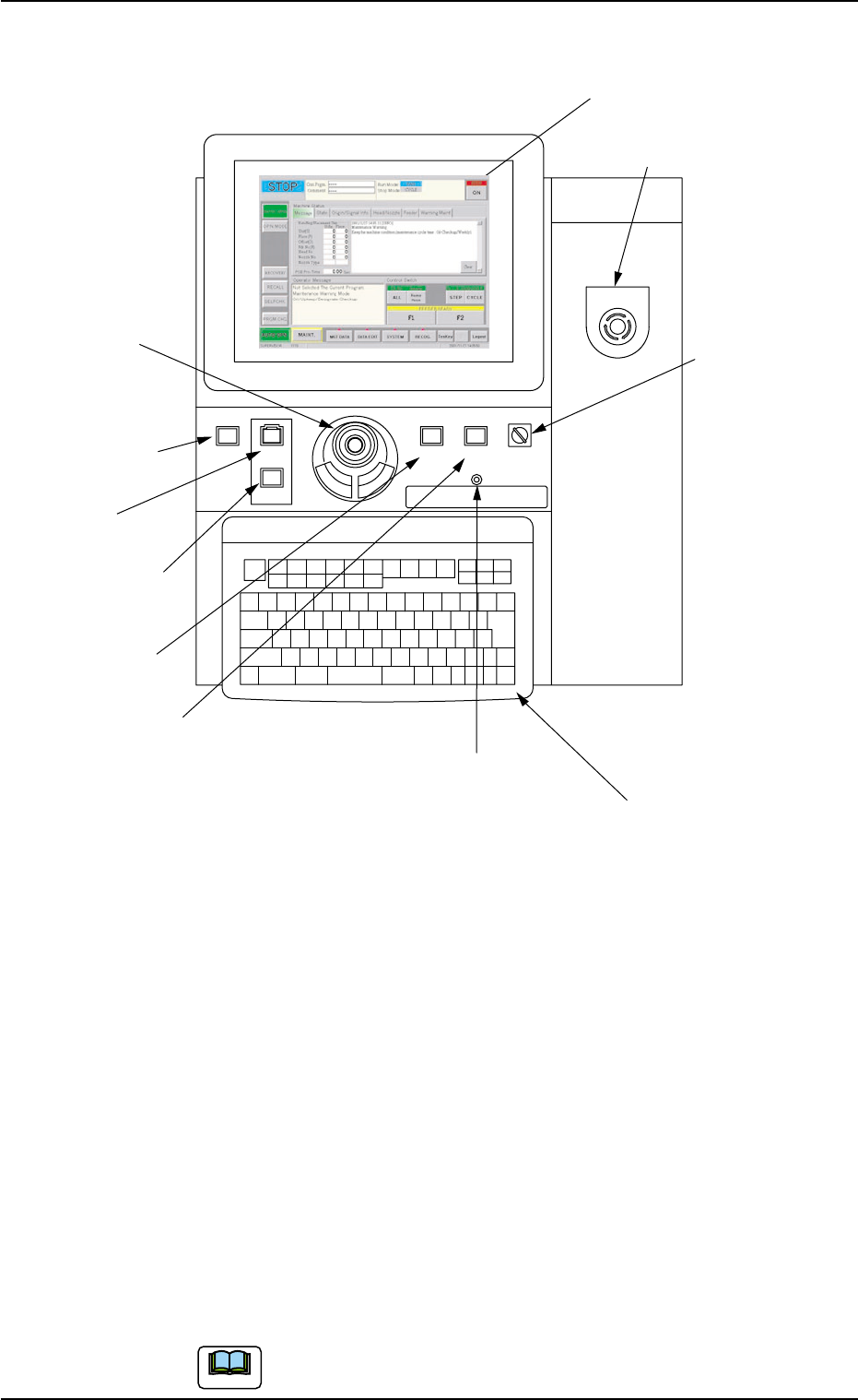
2.3.3 Front Operation Panel
Fig. 1A11
Arranged on the operation panel are switches and buttons required to
operate the machine.
The machine is provided with front and rear operation panels and can
be operated from either one of the panels. Panel selection is possible
with the [PNL CHANGE] buttons.
*1 [POWER ON] Button
• This button is used to turn on the power for operations.
*2 [START] Button
• This button is used to start the automatic operation.
The automatic operation can be started only when the lamp is flickering.
• While the lamp of this button is ON, it indicates that the machine is running
automatically.
When the [STOP] button is pressed during automatic operation, the lamp
extinguishes.
The lamp is kept ON while each device is being zeroed.
2.3 Operational Measures
0305-001 1-13 AIL01EOPP
POWER ON
STOP
START
ENABLE
RUN SETUP
OPERATION
LOCK
PNL CHANGE
*1 [POWER ON]
Button
*2 [START] Button
*3 [STOP] Button
*9 Keyboard
*8 [EMERGENCY STOP]
Switch
*7 [OPERATION]
Switch
*5 [PNL CHANGE] Button
*4 [ENABLE] Button
*11 Front Touch Screen
*6 [LOCK] Lamp
*10 Pointing Device
EMERGENCY STOP
Note

*3 [STOP] Button
• This button is used to stop the automatic operation.
• When this button is pressed during X/Y table test, the test operation stops.
• When this button is pressed during zeroing operation, the zeroing opera-
tion of each device is interrupted, excluding the P.C.B. transfer.
*4 [ENABLE] Button
• When the [ON] button (entitled "MOVE") is pressed on the touch screen,
the lamp of the [ENABLE] button illuminates for two seconds. When the
[ENABLE] button is pressed with its lamp "ON", the machine performs
various operations selected in the operation sheets.
*5 [PNL CHANGE] Button
• This button is used to select either the front or the rear operation panel.
(a) The other operation panel can be selected by pressing the
[PNL CHANGE] button on the unavailable (invalid) side only
when the currently selected panel is not set in the "Operation
Locked" mode.
(b) While the LED of this button is ON, the followings become
available.
Front Touch Screen
[START] Button
[STOP] Button
[ENABLE] Button
[OPERATION] Switch
[EMERGENCY STOP] Switch
Pointing Device
Keyboard
(c) The [STOP] button and [EMERGENCY STOP] switch are al-
ways available regardless of the [PNL CHANGE] button.
(d) When the panel operation is not locked and the [STOP] button
on the unselected operation panel is pressed, the operation
panel on the pressed button side becomes activated automati-
cally.
• When this button is pressed with the LED being "ON", only the front opera-
tion panel becomes available in operations (Operation Locked) and the
[LOCK] lamps on both front and rear operation panels illuminate.
To cancel the "LOCK" mode, press this button again.
2.3 Operational Measures
0305-001 1-14 AIL01EOPP
Note
*6 [LOCK] Lamp
• While the lamp is ON, it indicates that the selected operation is locked.
• When the operation panel is operated from the unavailable side, the [LOCK]
lamp flickers.
To cancel the flickering of the lamp, press the [PNL CHANGE] button and
follow the steps to set the operation-lock mode again.
*7 [OPERATION] Switch
• The selection key must be inserted to change over the [OPERATION] switch
to "RUN" or "SETUP".
The [OPERATION] switch must be set to the "RUN" side for automatic
operation.
The switch can be changed over to "RUN" or "SETUP" only when
the machine is in the "STOP" mode.
• When the switch is changed to the "SETUP" side, the machine is set as
follows.
(a) The red, yellow, and green lamps of the light tower will illu-
minate (initial setting of the machine upon shipment).
(b) The following operations are prohibited regardless of the front
safety door condition (opened/closed).
Automatic Operation, P.C.B. Transfer (Cycle) Operation, Ze-
roing Operation, Device Test, Unit Adjustment, and Teach-
ing Operation
A single operation of each menu is possible though its
continuous operation is prohibited.
(c) Operations automatically become available on the front op-
eration panel (operations locked).
No operations are accepted on the rear operation panel.
• When the [OPERATION] switch is set to the "SETUP"
side, the interlock function of the front safety door is
deactivated and it may cause critical injury to the
operator.
• Do not operate the machine with the [OPERATION]
switch in the "SETUP" mode except for the setup
operations.
• Do not keep the selection key inserted unless nec-
essary. The key shall be stored by the person in
charge.
• When the selection key is turned forcibly, the switch
may be damaged.
2.3 Operational Measures
0511-003 1-15 AIL01EOPP
Note
Note
DANGER