DECAN_S1_Troubleshooting_Guide(Eng_Ver1.3)_Print_Web.pdf - 第182页
1-158 Next Generation, Multi-Functional Plac er DECAN S1 Troubleshooting Guide In the case of the asy mmetrical component, register it manually . Select the error occurred pa rt from ‘Part’ of the P CB Edit menu and …

1-157
System Messages of the MMI and Solutions
$ad22 During auto teaching, an error of negative number for the recognized component size
(%d) occurred.
[Problem]
An error occurred due to H/W problem or S/W problem.
[Solution]
Turn off power to the machine in the usual way. Wait 5 seconds, turn back on and
reboot the system.
$ad30 The difference in recognized width values(%d, %d) of lead group(%d, %d) is big
when performing ‘Auto Teach’.
[Problem]
The difference in the recognized lead width between two lead groups is big.
Lead group of the component is asymmetrical.
Lighting setup is inadequate.
[Solution]
In the case of the asymmetrical component, register it manually.
Select the error occurred part from ‘Part’ of the PCB Edit menu and set the
illumination so that all lead groups are evenly illuminated.
$ad31 The difference in the recognized length(%d, %d) of the lead groups(%d, %d) is big
when performing ‘Auto Teach’.(Allowable value: %d)
[Problem]
The difference in the recognized lead width between two lead groups is big.
The lead group of the components is asymmetrical.
Lighting setup is inadequate.
[Solution]
In the case of the asymmetrical component, register it manually.
Select the error occurred part from ‘Part’ of the PCB Edit menu and set the
illumination so that all lead groups are evenly illuminated.
$ad32 Difference between the recognized pitch(%d, %d) of lead groups(%d, %d) during
‘Auto Teach’ is big.(Allowable value: %d)
[Problem]
The difference in the recognized lead pitch between two lead groups is big.
The lead group of the components is asymmetrical.
Lighting setup is inadequate.
[Solution]

1-158
Next Generation, Multi-Functional Placer DECAN S1 Troubleshooting Guide
In the case of the asymmetrical component, register it manually.
Select the error occurred part from ‘Part’ of the PCB Edit menu and set the
illumination so that all lead groups are evenly illuminated.
$ad33 The difference in the recognized foot value(%d, %d) between the lead groups(%d,
%d) when performing ‘Auto Teach’ is big.(Allowable value: %d)
[Problem]
The difference in the recognized lead foot between two lead groups is big.
The lead group of the components is asymmetrical.
Lighting setup is inadequate.
[Solution]
In the case of the asymmetrical component, register it manually.
Select the error occurred part from ‘Part’ of the PCB Edit menu and set the
illumination so that all lead groups are evenly illuminated.
$ae03 Failed in recognizing the fiducial mark.
[Problem]
The fiducial mark was not recognized.
The fiducial mark is not within the range of recognition, or defective.
The fiducial data or lighting setup is inadequate.
[Solution]
Check fiducial data and lighting setup, and readjust them. Please refer to section “6.3
Fiducial Mark Setup” of the Administrator’s Guide.
1.4.12. Software debug Related Error [$b000~$bfff]
$bbbb Assert fault has occurred. [MPU_STOP LEVEL]
[Problem]
An assert fault has occurred due to H/W problem or S/W problem.
[Solution]
Turn off power to the machine in the usual way. Wait 5 seconds, turn back on and
reboot the system.
$bc00 Equipment is not ready. [FREEZE LEVEL]
[Problem]
This error occurs when the equipment is driven without pressing the ready switch.
[Solution]
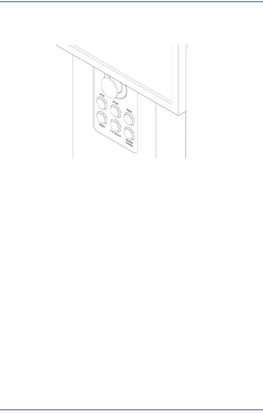
1-159
System Messages of the MMI and Solutions
Turn off the Buzzer by pressing the “STOP” button.
Switch the machine to “IDLE” mode by pressing the “RESET” button.
Supply power to the motor of the machine by pressing the “READY” button.
$bc05 Nozzle is blocked. [FREEZE LEVEL]
[Problem]
Nozzle is actually blocked with foreign matter.
The vacuum level was incorrectly measured due to fault of vacuum sensor.
Nozzle data setting error.
[Solution]
Turn off the Buzzer by pressing the “STOP” button.
Switch the machine to “IDLE” mode by pressing the “RESET” button.
Clean the nozzle if there is foreign matter at the nozzle inlet. Please refer to section
“Checking and cleaning the nozzle” of the Maintenance Handbook.
Check the vacuum sensor, and perform a vacuum test on the head showing in
“Vacuum” of the “Diagnosis” menu.