Micron Machine Settings Issue 3 LoRes.pdf - 第18页
CAMERA Vision Height Setting A Camera System Module W ARNING Standard Rails: 78mm -0.0mm +0.2mm MTR Rails: 79.5mm -0.0mm +0.2mm T op of Board Metric Rule Underside of Stencil A 4 1 5 2 6 3 BOARD CLAMPS 14
CAMERA
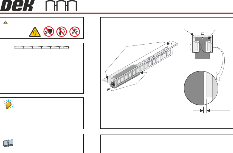
Y Axis Magnet Track and Forcer Linear Motors
0.5mm
Setting A
WARNING
Camera System Module
A
Test both gaps, on
both ends of the forcer
Y Forcer And Magnet Track
(Support brackets and fixings removed for clarity)
Magnet Track
Adjustment Screw (2)
View on Arrow A
Forcer to Magnet Track
Air Gap (both sides)
0.5mm Min
Forcer
Magnet Track
41 52 63
Strong Magnetic Force
))
((
A
13
CAMERA
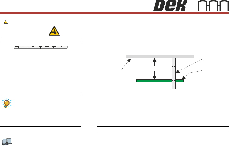
Vision Height
Setting A
Camera System Module
WARNING
Standard Rails: 78mm -0.0mm +0.2mm
MTR Rails: 79.5mm -0.0mm +0.2mm
Top of Board
Metric Rule
Underside
of Stencil
A
41 52 63
BOARD CLAMPS
14
CHASE
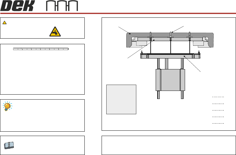
Chase to Table Level
Range of readings not to exceed 0.15mm
Setting
A datum reading is taken from the
centre hole E.
Graphic shows the ASM.
Readings are the same for the ASM,
cast C chase and machined C chase.
The range of readings must not
exceed 0.15mm of the datum.
Machined C Chase Module
ASM Module
BOARD CLAMPS
WARNING
A B
C D
E
A
B
C
D
E
mm
mm
mm
mm
mm
Record the five dimensions:
Test Plate
(plan view)
Depth Micrometer
Test Plate
Adjustable Screen Mount
Rising Table
View on Front of Machine
41 52 63
15