Micron Machine Settings Issue 3 LoRes.pdf - 第19页
CHASE Chase to T able Level Range of readings not to exceed 0.15mm Setting A datum reading is taken from the centre hole E. Graphic shows the ASM. Readings are the same for the ASM, cast C chase and machined C chase. The…
CAMERA
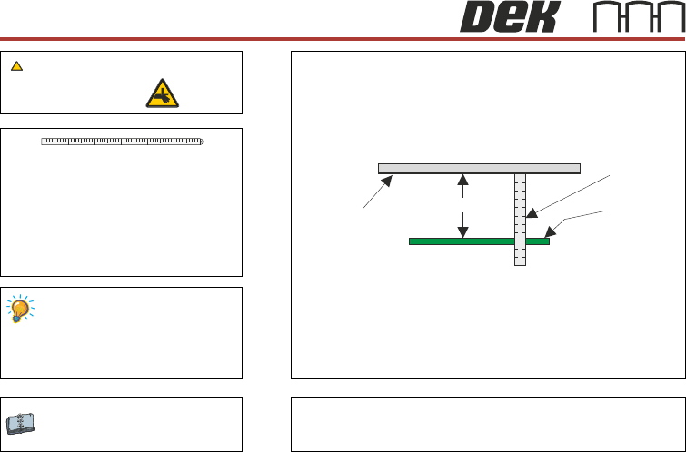
Vision Height
Setting A
Camera System Module
WARNING
Standard Rails: 78mm -0.0mm +0.2mm
MTR Rails: 79.5mm -0.0mm +0.2mm
Top of Board
Metric Rule
Underside
of Stencil
A
41 52 63
BOARD CLAMPS
14
CHASE
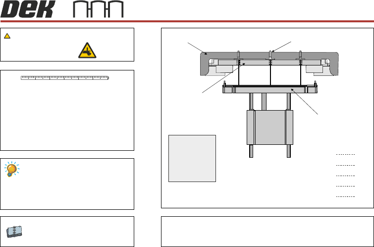
Chase to Table Level
Range of readings not to exceed 0.15mm
Setting
A datum reading is taken from the
centre hole E.
Graphic shows the ASM.
Readings are the same for the ASM,
cast C chase and machined C chase.
The range of readings must not
exceed 0.15mm of the datum.
Machined C Chase Module
ASM Module
BOARD CLAMPS
WARNING
A B
C D
E
A
B
C
D
E
mm
mm
mm
mm
mm
Record the five dimensions:
Test Plate
(plan view)
Depth Micrometer
Test Plate
Adjustable Screen Mount
Rising Table
View on Front of Machine
41 52 63
15
CHASE
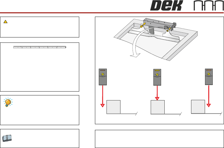
Screen Position Sensor
ASM Module
Machined C Chase Module
WARNING
41 52 63
Sensor Behind Screen
Adjust the sensitivity anti-clockwise until LED
extinguishes,
Turn the sensitivity clockwise until LED
illuminates.
Turn the sensitivity clockwise a further half turn.
Move the rear screen frame backwards and
forwards under the sensor to ensure that the test
LED is only activiated under the screen.
Sensor Over Screen Frame Sensor Over Screen
+
-
Test LED Off
+
-
Test LED On
+
-
Test LED Off
16