TUT-CP842-Oper guide-preliminary.pdf.pdf - 第16页
1. Circuit breaker Set to the ON position to supply power to the machine. 2. Oil cooler The oil cooler supplies oil for lubrication to the index unit in the cam box. 3. Device Set alarm Lights when device loading has not…
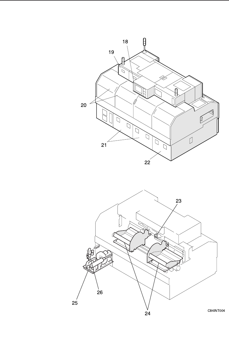
Rear View
Chapter 1: Machine Configuration
Preliminary
1-5CP-842E/842ME Operator’s Guide

1. Circuit breaker
Set to the ON position to supply power to the machine.
2. Oil cooler
The oil cooler supplies oil for lubrication to the index unit in the cam box.
3. Device Set alarm
Lights when device loading has not been completed.
4. Cam box
The machine's drive mechanism is housed in the cam box.
5. Signal tower
A red, yellow, or blue (green) light will come on or flash on-and-off
depending on the status of the machine during production.
6. Operation box 1
Machine operation is carried out from this box. Commands are issued by
pressing the buttons on the touch panel.
7. Conveyor width adjusting handle
This handle is used for adjusting the width of the conveyor.
8. Waste tape box
The waste tape cut by the tape cutter is accumulated for discard in this
box.
9. Control box
The machine control system is housed in these boxes.
10. Placing head
The placing head is used for part pickup and placement.
11. Index unit
This unit rotates the placement head turret thereby positioning each place-
ment head at the respective stations.
12. Mark camera
This camera is used for reading fiducial marks.
13. Out-conveyor
The out-conveyor is used to unload finished panels to the next machine.
14. Out-carrier
The out-carrier conveyors the panels between the XY-table and out-con-
veyor.
15. XY-table
Panels are moved to the part placement position on the XY-table.
16. In-carrier
The in-carrier conveyors the panels between the in-conveyor and XY-
table.
17. In-conveyor
The in-conveyor receives panels from the previous machine.
Chapter 1: Machine Configuration
Preliminary
1-6 CP-842E/842ME Operator’s Guide

18. Operation box 2
This box is used to carry out control from the rear of the machine.
19, 21.Servo boxes
The servo amps are stored here.
20. Rear cover
Slide the cover to open and close.
22. Transformer box
Contains the transformer, servo amplifier, and UPS, etc.
* UPS: Uninterrupted Power Supply
23. Waste tape disposal unit
This cutter is used to cut the tape that is left after each part is picked.
24. Device table
A feeder pallet is set on each device table, on which the feeders are
moved to the pick-up position.
25. Vacuum pump
Two vacuum pumps supply vacuum for part pickup and waste tape
suction.
26. Filter regulator
The external air supply is connected to the filter regulator. Air pressure
adjustments can also be made here.
Chapter 1: Machine Configuration
Preliminary
1-7CP-842E/842ME Operator’s Guide