TUT-CP842-Oper guide-preliminary.pdf.pdf - 第19页
9. Z-axis Moves the panel up and down in accordance with the height of parts as parts are placed. This axis also drives the board lifter . 10. NC-axis This axis turns the nozzle change unit clutch. 1 1. RQ-axis (reverse …
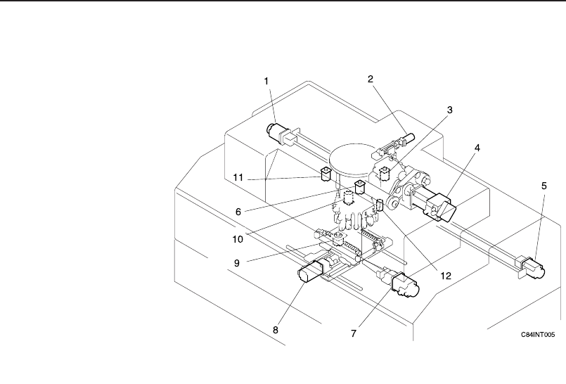
Servo Control Axes
Note: Although this diagram shows the CP-842ME, it applies to the CP-842E
as the servo control axis locations are the same.
1. D1-axis
Moves the feeders loaded on device table 1 to the respective pickup
positions.
2. NZ-axis
This axis moves the placement head up and down for part pickup.
3. PQ-axis (pre-theta)
This axis is used to provisionally rotate parts prior to FQ (fine theta)
rotation.
4 C-axis
Drives the index unit and cam axes located in the cam box.
5. D2-axis
Moves the feeders loaded on device table 2 to the respective pickup
positions.
6. FQ-axis (fine theta)
This axis is used to rotate parts to their final placement angle.
7. X-axis
Moves the XY-table to the left and right.
8. Y-axis
Moves the XY-table forward and backward.
Chapter 1: Machine Configuration
Preliminary
1-8 CP-842E/842ME Operator’s Guide
9. Z-axis
Moves the panel up and down in accordance with the height of parts as
parts are placed. This axis also drives the board lifter.
10. NC-axis
This axis turns the nozzle change unit clutch.
11. RQ-axis (reverse theta)
This axis returns placing heads to their origin position after part place-
ment.
12. NY-axis
Moves the nozzle in the Y-direction according to pickup offsets.
Machine Configuration
C84INT006E
Cam box
Index units
Placing heads
Stations 1-16
Feeders
Tape cutter
Pallet supply device
*PCU (Pallet Change Unit)
Parts camera
Mark camera
Carrier loader
CP-842E/CP-842ME
Part placement system
Part supply system
Vision system
Panel conveyance
system
Electrical control
system
Pneumatic control
system
Machine functions
Operation panel
Control box
Servo box (Servo BKT)
UPS (Uninterrupted Power Supply
Unit)
*:CP-842ME Option
Chapter 1: Machine Configuration
Preliminary
1-9CP-842E/842ME Operator’s Guide
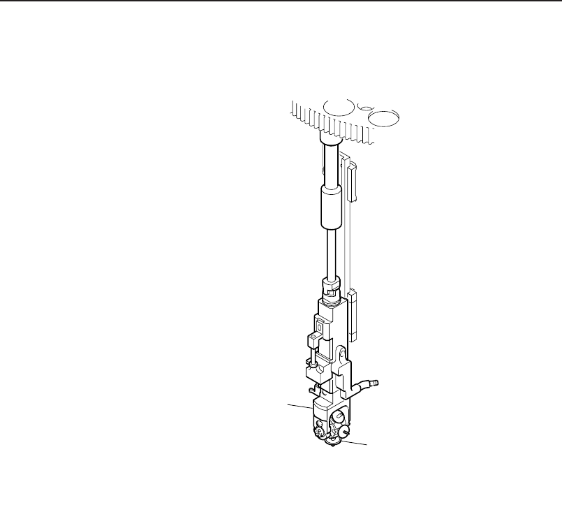
Part Placement System
Placing Head
There are 16 placing heads positioned around the circumference of the turret.
Each placing head consists of nozzles, a nozzle holder, and nozzle shaft as well
as other components.
Up to 6 nozzles can be loaded on a nozzle holder thereby allowing nozzles to
be used in accordance with the size and characteristics of the parts to be han-
dle.
C84INT007E
Rotary holder
Nozzle
Chapter 1: Machine Configuration
Preliminary
1-10 CP-842E/842ME Operator’s Guide