TUT-CP842-Oper guide-preliminary.pdf.pdf - 第8页
Notation Conventions Used in This Manual The notation conventions employed in this manual are described below . General notation Notation sample Explanation POWER ON, EMERGENCY STOP Buttons or switches on the machine are…

About This Manual
Manual Structure
This manual has been created to familiarize the operator with standard operating procedures. The
procedures included are split into several steps, each of which should be read and then carried out
at the machine. The manual itself is also split into several chapters, and after an initial
introduction to the machine, the order of the chapters is designed to roughly reflect the order in
which the machine will be operated during actual production. For a more detailed explanation of
machine operation and workings, refer to the CP-842E/842ME System Reference or
CP-842E/842ME Mechanical Reference manuals.
Chapter 1: Machine Configuration
This chapter provides illustrations and basic introductions to each of the major components of the
machine.
Chapter 2: Starting and Stopping the Machine
This chapter explains how to start and stop the machine, and select the various operation modes.
Chapter 3: Preparing for Production
This chapter explains how to select a production program, set the production quantity, and
perform other operations necessary to ready the machine for production.
Chapter 4 Starting Production
This chapter explains how to ready and check the nozzles, load a panel, and then commence
operation.
Chapter 5: Stopping the Machine
This chapter describes the various ways in which the machine can be stopped.
Chapter 6: Finishing Production
This chapter describes the procedure for stopping automatically upon completion of the scheduled
lot or the current panel.
Chapter 7: Maintenance
Routine maintenance procedures are detailed in this chapter.
Chapter 8: Production Support Functions
Several other procedures that may be performed during operation are detailed in this chapter.
About This Manual
Preliminary
1CP-842E/842ME Operator’s Guide

Notation Conventions Used in This Manual
The notation conventions employed in this manual are described below.
General notation
Notation sample Explanation
POWER ON, EMERGENCY STOP Buttons or switches on the machine are written as they
display at the machine.
[AUTO], [STEP] Machine commands are enclosed by square brackets.
About Symbols
To avoid injury to persons and damage to the machine, Fuji employs a number of messages and
symbols that are used in manuals and on the machines. Be sure you understand the meanings of
these symbols before reading the manual.
Hazard warnings are divided into the following three classes:
Notation sample Explanation
DANGER The hazard or unsafe practice will cause severe injury
or death.
WARNING The hazard or unsafe practice may cause severe injury
or death.
CAUTION The hazard or unsafe practice may lead to personal
injury or damage to the machine.
About This Manual
Preliminary
2 CP-842E/842ME Operator’s Guide
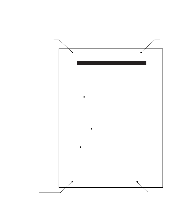
How to Read This Manual
The information in this manual is generally arranged as shown below.
Chapter title
This is the title of the chapter.
Edition number
This manual is updated on a chapter-by-chapter basis. The edition numbers are revised when the
manual content is revised or updated. The edition number for the manual as a whole is found on
the front cover of the manual.
Important: This manual can be stored in a loose-leaf binder to allow easy replacement
or addition of pages. To keep your manual up-to-date at all times, check the
edition numbers against the numbers indicated in the table of contents. Any
additional or updated sections of this manual can be
downloaded as required from Fuji's website (http://www.fuji.co.jp.).
Body
Step
Edition numberChapter title
Manual title
Page number
Notes:
CP84T001E
Setting the Device Table Mode
Select the method in which the device tables are to be used (Table mode) in
accordance with production.
<Explanation of table modes>
Joint mode:
The device tables D1 and D2 are operated together as a single device table.
This mode is used for production programs that have a large number of parts.
Joint resupply mode:
Joint resupply mode is basically the same as the standard joint mode in that
both tables are used in production. However, in joint resupply mode, the table
which is inactive in moved to the retract position until required, and feeders
can be set or removed at this position without interrupting production.
Device Change mode:
One of the device tables D1 or D2 is used in production while the other table
is kept in the standby position for use as a reserve. When a part runs out on
the device table in use, a switch is made to the other device table and
production continues. The relevant device slots on each table must be loaded
with the same parts.
Changeover mode:
One of the device tables D1 or D2 is used for production while parts are
switched on the other to ready it for the next production run.
Note: When either the “Device Change Mode” or the “Changeover Mode” is
selected, the [Original Table] setting described below must also be
specified.
Procedure
1. Select [Operation] from the [Main] screen.
2. Select the table mode that is to be used in production. Select
either "Joint", "Device Change", or "Changeover".
3. Press [Close] to return to the [Main] screen.
3.3 Device Tables
Chapter 3: Preparing for Production
Preliminary
3-10 CP-842E/842ME Operator’
s Guide
About This Manual
Preliminary
3CP-842E/842ME Operator’s Guide