D4+circuit(2006).pdf - 第101页
3 - 6 0303235 2-040 101LD3 Distributo r , sector 2 (sh. 4 of 4) Verteiler Sektor 2 Distributor sector 2 03032352-040101LD3 4 23.03.2005 Huber M. RS02 HM 07.06.05 S1: switch status FS0 3 modi fi cat ion X 21b f 19.05. 05 …
3 - 5
03032352-040101LD3 Distributor, sector 2 (sh. 3 of 4)
Verteiler Sektor 2
Distributor sector 2
03032352-040101LD3
4
23.03.2005
Huber M.RS02
HM
07.06.05S1: switch status
FS03
modification X21bf 19.05.05
HM
HM
402216
FS04
16.01.06
Orig. Repl. by.Repl. f.
W
e
i
t
e
r
g
a
b
e
s
o
w
i
e
V
e
r
v
i
e
l
f
ä
l
t
i
g
u
n
g
d
i
e
s
e
r
U
n
t
e
r
l
a
g
e
,
V
e
r
w
e
r
t
u
n
g
u
n
d
M
i
t
t
e
i
l
u
n
g
i
h
r
e
s
I
n
h
a
l
t
s
n
i
c
h
t
g
e
s
t
a
t
t
e
t
,
s
o
w
e
i
t
n
i
c
h
t
a
u
s
d
r
ü
c
k
l
i
c
h
z
u
g
e
s
t
a
n
d
e
n
.
Z
u
w
i
d
e
r
h
a
n
d
l
u
n
g
e
n
v
e
r
p
f
l
i
c
h
t
e
n
z
u
S
c
h
a
d
e
n
e
r
s
a
t
z
.
A
l
l
e
R
e
c
h
t
e
v
o
r
b
e
h
a
l
t
e
n
,
i
n
s
b
e
s
o
n
d
e
r
e
f
ü
r
d
e
n
F
a
l
l
d
e
r
P
a
t
e
n
t
e
r
t
e
i
l
u
n
g
o
d
e
r
G
M
-
E
i
n
t
r
a
g
u
n
g
.
P
r
o
p
r
i
e
t
a
r
y
d
a
t
a
,
c
o
m
p
a
n
y
c
o
n
f
i
d
e
n
t
i
a
l
.
A
l
l
r
i
g
h
t
s
r
e
s
e
r
v
e
d
.
C
o
n
f
i
e
a
t
i
t
r
e
d
e
s
e
c
r
e
t
d
'
e
n
t
r
e
p
r
i
s
e
.
T
o
u
s
d
r
o
i
t
s
r
e
s
e
r
v
e
s
.
C
o
m
u
n
i
c
a
d
o
c
o
m
o
s
e
g
r
e
d
o
e
m
p
r
e
s
a
r
i
a
l
.
R
e
s
e
r
v
a
d
o
s
t
o
d
o
s
o
s
d
i
r
e
i
t
o
s
.
C
o
n
f
i
a
d
o
c
o
m
o
s
e
c
r
e
t
e
i
n
d
u
s
t
r
i
a
l
.
N
o
s
r
e
s
e
r
v
a
m
o
s
t
o
d
o
s
l
o
s
d
e
r
e
c
h
o
s
.
21 786543
21 786543
A
B
C
D
E
F
A
B
C
D
E
F
Date
Author
Checked
StandardNameModificationStat. Date
Sheet
Designer 9
Copyright reserved
SIEMENS AG
Item name / Benennung
of
Document no. /
Dokumentennummer:
SIPLACE D4
2
3
X3rb
X5rb
X6rb
X7rb
X9rb
1
2
3
4
5
7
6
8
1
2
3
4
5
7
6
8
1
2
3
4
5
7
6
8
1
2
3
4
5
7
6
8
1
2
3
4
5
7
6
8
CAN-Ein/Ausgabe-Modul 2 /
CAN input/output module 2
nc
nc
nc
nc
nc
nc
nc
nc
nc
nc
GND
24V
24V
24V
24V
GND
GND
GND
nc
nc
nc
nc
nc
nc
nc
nc
nc
nc
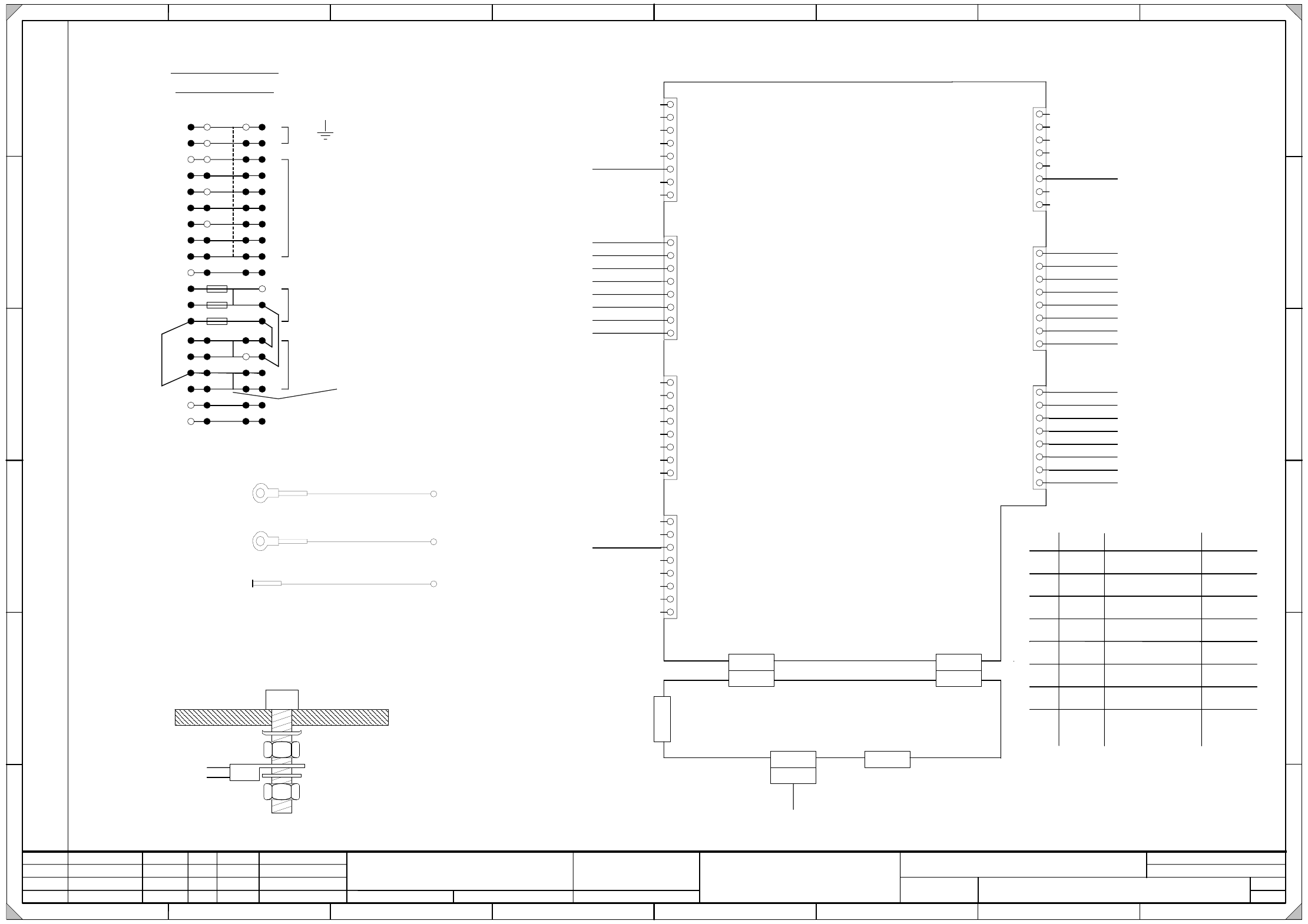
K1_A1
X1rb X2rb
X10bf_6
Ctrl_compressed air St_DruckluftHauptventil
M_DrucksensorHauptventil S_PressureSensor
nc
nc
nc
nc
nc
nc
nc
X200_15A
X200_15B
X200_14A
X200_14B
X200_8A
X200_9A
X200_7A
X200_6A
X200 terminal overview
Klemmenuebersicht X200
1
2
acb
+24V
5
4
6
7
8
9
10
17
13
14
15
11
12
16
PE
Erde
Ground
Querbruecker Jumper
GND
d
+5V
1P40V
P8V
+24V
3
X4rb
1
2
3
4
5
7
6
8
X17bf_1
M_Pip.Links(auf)_2a S_LeftNozzles(open)
M_Pip.Links(auf)_2b S_LeftNozzles(open)
M_Pip.Links(auf)_3a S_LeftNozzles(open)
M_Pip.Links(auf)_3b S_LeftNozzles(open)
M_Pip.Rechts(zu)_2b S_RightNozzles(closed)
M_Pip.Rechts(zu)_2a S_RightNozzles(closed)
M_Pip.Rechts(zu)_3a
S_RightNozzles(closed)
M_Pip.Rechts(zu)_3b
S_RightNozzles(closed)
X17bf_3
X18bf_1
X18bf_3
X19bf_1
X19bf_3
X20bf_3
X20bf_1
X8rb
1
2
3
4
5
7
6
8
Ctrl_Green Indicator1 St_GrüneLampe1
Ctrl_Fault Indicator1 St_StörLampe1
Ctrl_Fault Indicator2 St_StörLampe2
X16bf_2
X16bf_1
X16bf_3
X16bf_4
Ctrl_Green Indicator2 St_GrüneLampe2
Ctrl_ValveNozzles St_VentilPipetten_2a
Ctrl_ValveNozzles St_VentilPipetten_2b
Ctrl_ValveNozzles St_VentilPipetten_3a
Ctrl_ValveNozzles St_VentilPipetten_3b
X17bf_5
X18bf_5
X19bf_5
X20bf_5
nc
nc
A1 (rb)
KSP-CAN-E/A-Modul2
KSP CAN I/O module 2
X200_1A
Erdung PE Verteiler
Distributor grounding (PE)
BK (UL) / 0,5mm²
BK (UL) / 0,5mm²
BK (UL) / 0,5mm²
BK (UL) / 0,5mm²
BK (UL) / 0,5mm²
BK (UL) / 0,5mm²
BK (UL) / 0,5mm²
BK (UL) / 0,5mm²
BK (UL) / 0,5mm²
GNYE (UL) / 2,5mm²
BK (UL) / 0,5mm²
BK (UL) / 0,5mm²
BK (UL) / 0,5mm²
BK (UL) / 0,5mm²
BK (UL) / 0,5mm²
BK (UL) / 0,5mm²
BK (UL) / 0,5mm²
BK (UL) / 0,5mm²
BK (UL) / 0,5mm²
OG (UL) / 1,5mm²
OG (UL) / 1,5mm²
OG (UL) / 1,5mm²
OG (UL) / 1,5mm²
WH (UL) / 1,5mm²
WH (UL) / 1,5mm²
WH (UL) / 1,5mm²
WH (UL) / 1,5mm²
P2 Sicherung P2 fuse
X2re X1re
X
3
r
e
A2 (re)
CAN-Interface
X4re X5re
CAN-BUS
500KBit/s
CAN bus
500 Kbit/s
Zu X1rf A3 (rf)
To X1rf A3 (rf)
CAN-BUS 1Mbit/s
CAN bus 1Mbit/s
WH (UL) / 1,5mm²
X200_3D
18
P3 Sicherung P3 fuse
GND
X200_2C
Erdung PE X1bf
X1bf grounding (PE)
GNYE (UL) / 2,5mm²
S1.1 Gateway ON: Gateway on
OFF: Gateway off
Switch Function Coding
Plattform ON: Slio emulation
OFF: CAN i/o-module
S1.3 Stellung ON: not used
OFF: not used
S1.4 ON: Distributor sector 2
OFF: Distributor sector 4
S1.5 Nicht benutzt ON: not used
OFF: not used
1-Wire ON: 1-Wire MA
OFF: 1-Wire PC
S1.7 Nicht benutzt ON: not used
OFF: not used
S1.8 Abschluss-
widerstand
ON: not used
OFF: not used
S1 switch status on the CAN input/output module 2 (A1)
OFF
Switch status
S1.2
S1.6
Stellung
ON
OFF
ON
OFF
ON
OFF
OFF
19
Sicherung_24V
fuse_24V
X200_2A
Erdung PE Maschinenständer
Machine frame grounding (PE)
GNYE (UL) / 2,5mm²
length= 350mm
X4re
03047453
Schraube / Bolt
Kontaktscheibe / Contact washer
Mutter DIN439 / DIN439 nut
Kabelschuhring / Annular cable lug
Mutter DIN439 / DIN439 nut
Sperrkantscheibe / Serrated lock washer
Blech / Plate
Erdungsanschluss nach Bauvorschrift 90010850-XXXXXXBD4:
Grounding terminal according to d esign specification 90010850-XXXXXXBD4:
Schalter Funktion Kodierung Schalterstellung
S1 Schalterstellung am CAN Eingabe-/Ausgabemodul 2 (A1)
Platform
Location
Not used
Not used
Terminating
resistor
Location
3 - 6
03032352-040101LD3 Distributor, sector 2 (sh. 4 of 4)
Verteiler Sektor 2
Distributor sector 2
03032352-040101LD3
4
23.03.2005
Huber M.RS02
HM
07.06.05S1: switch status
FS03
modification X21bf 19.05.05
HM
HM
402216
FS04
16.01.06
Orig. Repl. by.Repl. f.
W
e
i
t
e
r
g
a
b
e
s
o
w
i
e
V
e
r
v
i
e
l
f
ä
l
t
i
g
u
n
g
d
i
e
s
e
r
U
n
t
e
r
l
a
g
e
,
V
e
r
w
e
r
t
u
n
g
u
n
d
M
i
t
t
e
i
l
u
n
g
i
h
r
e
s
I
n
h
a
l
t
s
n
i
c
h
t
g
e
s
t
a
t
t
e
t
,
s
o
w
e
i
t
n
i
c
h
t
a
u
s
d
r
ü
c
k
l
i
c
h
z
u
g
e
s
t
a
n
d
e
n
.
Z
u
w
i
d
e
r
h
a
n
d
l
u
n
g
e
n
v
e
r
p
f
l
i
c
h
t
e
n
z
u
S
c
h
a
d
e
n
e
r
s
a
t
z
.
A
l
l
e
R
e
c
h
t
e
v
o
r
b
e
h
a
l
t
e
n
,
i
n
s
b
e
s
o
n
d
e
r
e
f
ü
r
d
e
n
F
a
l
l
d
e
r
P
a
t
e
n
t
e
r
t
e
i
l
u
n
g
o
d
e
r
G
M
-
E
i
n
t
r
a
g
u
n
g
.
P
r
o
p
r
i
e
t
a
r
y
d
a
t
a
,
c
o
m
p
a
n
y
c
o
n
f
i
d
e
n
t
i
a
l
.
A
l
l
r
i
g
h
t
s
r
e
s
e
r
v
e
d
.
C
o
n
f
i
e
a
t
i
t
r
e
d
e
s
e
c
r
e
t
d
'
e
n
t
r
e
p
r
i
s
e
.
T
o
u
s
d
r
o
i
t
s
r
e
s
e
r
v
e
s
.
C
o
m
u
n
i
c
a
d
o
c
o
m
o
s
e
g
r
e
d
o
e
m
p
r
e
s
a
r
i
a
l
.
R
e
s
e
r
v
a
d
o
s
t
o
d
o
s
o
s
d
i
r
e
i
t
o
s
.
C
o
n
f
i
a
d
o
c
o
m
o
s
e
c
r
e
t
e
i
n
d
u
s
t
r
i
a
l
.
N
o
s
r
e
s
e
r
v
a
m
o
s
t
o
d
o
s
l
o
s
d
e
r
e
c
h
o
s
.
21 786543
21 786543
A
B
C
D
E
F
A
B
C
D
E
F
Date
Author
Checked
StandardNameModificationStat. Date
Sheet
Designer 9
Copyright reserved
SIEMENS AG
Item name / Benennung
of
Document no. /
Dokumentennummer:
SIPLACE D4
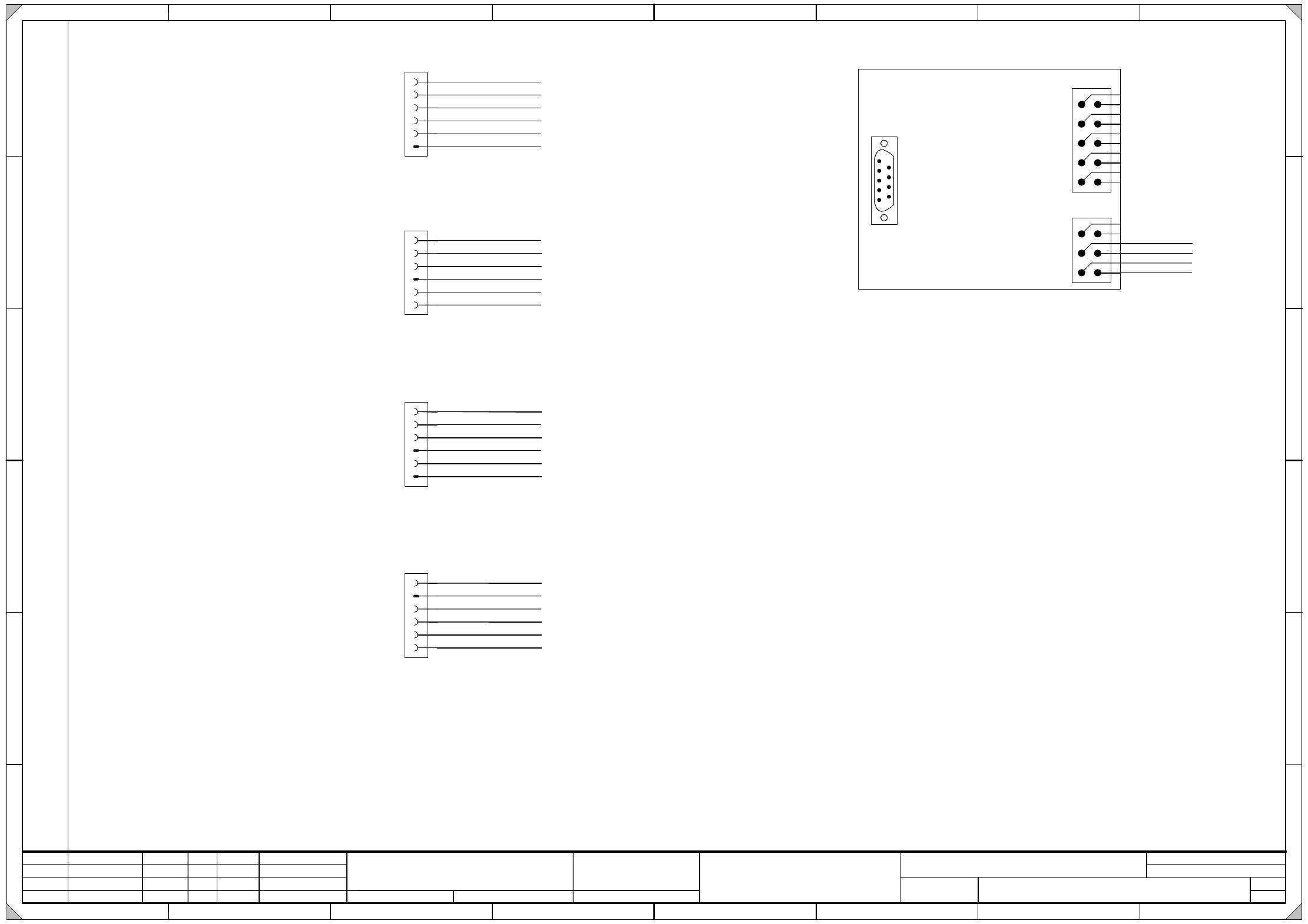
X17bf
1
2
3
4
5
6
S_LeftNozzles(open) M_PipettenLinks(auf)
Nozzle changer 2a
Pipettenwechsler 2a
S_RightNozzles(closed) M_PipettenRechts(zu)
Ctrl_ValveNozzles St_VentilPipetten
GND
+24V
GND
X18bf
1
2
3
4
5
6
S_LeftNozzles(open) M_PipettenLinks(auf)
Nozzle changer 2b
Pipettenwechsler 2b
S_RightNozzles(closed) M_PipettenRechts(zu)
Ctrl_ValveNozzles St_VentilPipetten
GND
+24V
GND
X19bf
1
2
3
4
5
6
S_LeftNozzles(open) M_PipettenLinks(auf)
Nozzle changer 3a
Pipettenwechsler 3a
S_RightNozzles(closed) M_PipettenRechts(zu)
Ctrl_ValveNozzles St_VentilPipetten
GND
+24V
GND
X20bf
1
2
3
4
5
6
S_LeftNozzles(open) M_PipettenLinks(auf)
Nozzle changer 3b
Pipettenwechsler 3b
S_RightNozzles(closed) M_PipettenRechts(zu)
Ctrl_ValveNozzles St_VentilPipetten
GND
+24V
GND
X4rb_1
X4rb_2
X8rb_1
X8rb_2
X4rb_3
X8rb_3
X4rb_7
X8rb_4
X4rb_4
X4rb_5
X4rb_6
X4rb_8
X200_4B, X18bf_4
X200_6B, X18bf_6
X200_16C, X18bf_2
X17bf_2, X19bf_2
X17bf_4, X19bf_4
X17bf_6, X19bf_6
X18bf_2, X20bf_2
X18bf_4, X20bf_4
X18bf_6, X20bf_6
X19bf_2
X19bf_4
X19bf_6
BK (UL) / 0,5mm²
BK (UL) / 0,5mm²
BK (UL) / 0,5mm²
BK (UL) / 0,5mm²
BK (UL) / 0,5mm²
BK (UL) / 0,5mm²
BK (UL) / 0,5mm²
BK (UL) / 0,5mm²
BK (UL) / 0,5mm²
BK (UL) / 0,5mm²
BK (UL) / 0,5mm²
BK (UL) / 0,5mm²
WH (UL) / 1,0mm²
WH (UL) / 1,0mm²
WH (UL) / 1,0mm²
WH (UL) / 1,0mm²
WH (UL) / 1,0mm²
WH (UL) / 1,0mm²
WH (UL) / 1,0mm²
WH (UL) / 1,0mm²
OG (UL) / 1,0mm²
OG (UL) / 1,0mm²
OG (UL) / 1,0mm²
OG (UL) / 1,0mm²
4
Von X4re CAN-Interface
A2 (re) 500 Kbit/s
From X4re CAN interface
A2 (re) 500Kbit/s
Zu X1bf Modul B
To X1bf B module
X1rf
CAN-Bus Abschluss
Be-Tisch
CAN bus terminator
Component table
A3 (rf)
SUBD
X3rf
X6bf_2
X3bf_2
Key
1
2
3
4
5
6
BK (UL) / 0,5mm²
BK (UL) / 0,5mm²
BK (UL) / 0,5mm²
BK (UL) / 0,5mm²
X200_3C
X1bf_C5
10
9
X2rf
8
7
6
5
4
3
2
1
Key
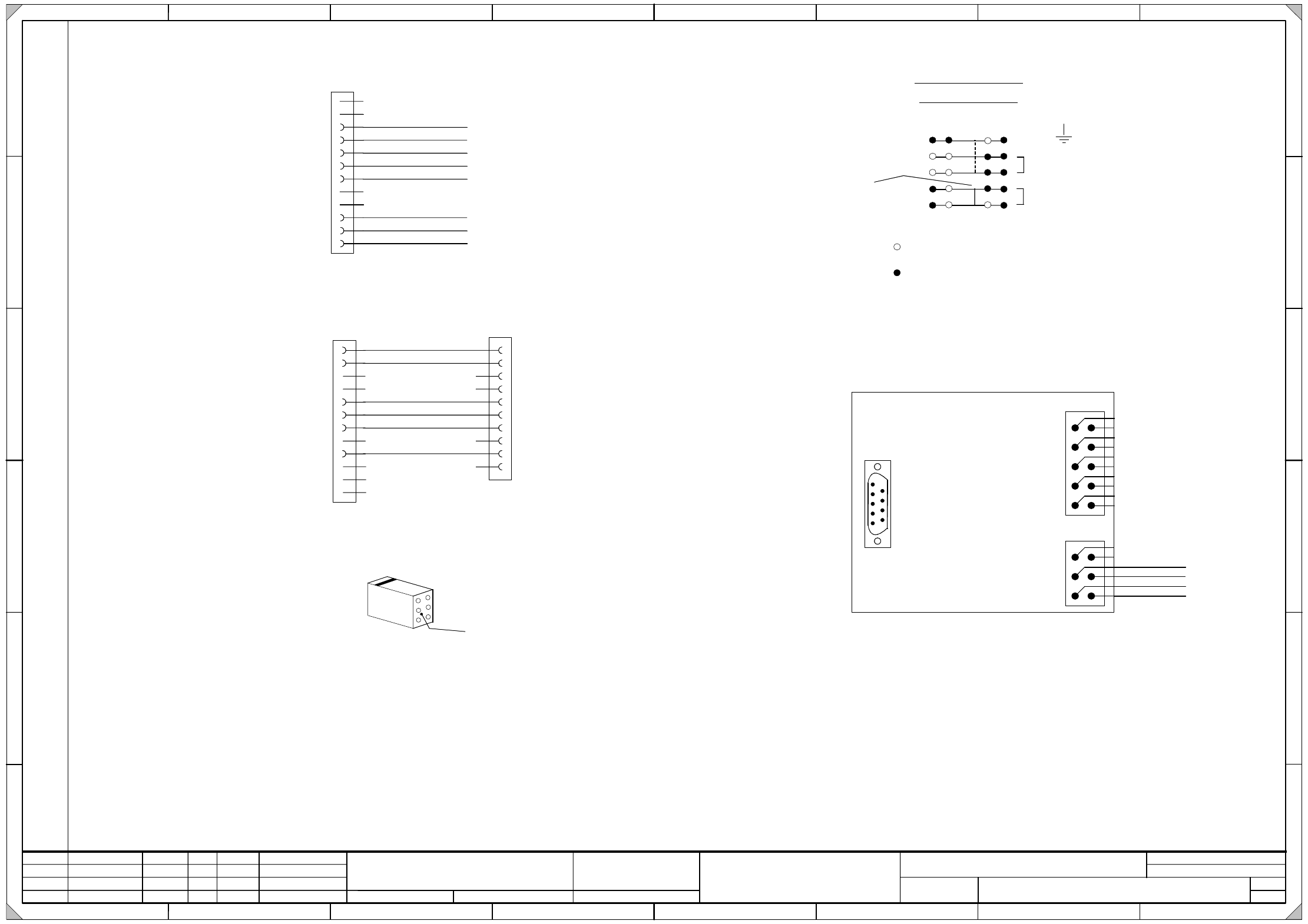
3 - 7
03032353-030101LD3 Distributor, sector 3 (sh. 1 of 2)
Verteiler Sektor 3
Distributor, sector 3
03032353-030101LD3
2
23.03.2005
Huber M.
HM
08.06.05P34 --> P40US02
FS03 16.01.06
HM
HM
15.06.05R120 eliminateRS02
402216
Orig. Repl. by.Repl. f.
W
e
i
t
e
r
g
a
b
e
s
o
w
i
e
V
e
r
v
i
e
l
f
ä
l
t
i
g
u
n
g
d
i
e
s
e
r
U
n
t
e
r
l
a
g
e
,
V
e
r
w
e
r
t
u
n
g
u
n
d
M
i
t
t
e
i
l
u
n
g
i
h
r
e
s
I
n
h
a
l
t
s
n
i
c
h
t
g
e
s
t
a
t
t
e
t
,
s
o
w
e
i
t
n
i
c
h
t
a
u
s
d
r
ü
c
k
l
i
c
h
z
u
g
e
s
t
a
n
d
e
n
.
Z
u
w
i
d
e
r
h
a
n
d
l
u
n
g
e
n
v
e
r
p
f
l
i
c
h
t
e
n
z
u
S
c
h
a
d
e
n
e
r
s
a
t
z
.
A
l
l
e
R
e
c
h
t
e
v
o
r
b
e
h
a
l
t
e
n
,
i
n
s
b
e
s
o
n
d
e
r
e
f
ü
r
d
e
n
F
a
l
l
d
e
r
P
a
t
e
n
t
e
r
t
e
i
l
u
n
g
o
d
e
r
G
M
-
E
i
n
t
r
a
g
u
n
g
.
P
r
o
p
r
i
e
t
a
r
y
d
a
t
a
,
c
o
m
p
a
n
y
c
o
n
f
i
d
e
n
t
i
a
l
.
A
l
l
r
i
g
h
t
s
r
e
s
e
r
v
e
d
.
C
o
n
f
i
e
a
t
i
t
r
e
d
e
s
e
c
r
e
t
d
'
e
n
t
r
e
p
r
i
s
e
.
T
o
u
s
d
r
o
i
t
s
r
e
s
e
r
v
e
s
.
C
o
m
u
n
i
c
a
d
o
c
o
m
o
s
e
g
r
e
d
o
e
m
p
r
e
s
a
r
i
a
l
.
R
e
s
e
r
v
a
d
o
s
t
o
d
o
s
o
s
d
i
r
e
i
t
o
s
.
C
o
n
f
i
a
d
o
c
o
m
o
s
e
c
r
e
t
e
i
n
d
u
s
t
r
i
a
l
.
N
o
s
r
e
s
e
r
v
a
m
o
s
t
o
d
o
s
l
o
s
d
e
r
e
c
h
o
s
.
21 786543
21 786543
A
B
C
D
E
F
A
B
C
D
E
F
Date
Author
Checked
StandardNameModificationStat. Date
Sheet
Designer 9
Copyright reserved
SIEMENS AG
Item name / Benennung
of
Document no. /
Dokumentennummer:
SIPLACE D4
1
Klemme frei / Terminal not used
Klemme gelegt / Terminal used
Jumper
Querbruecker
1
2
5
4
PE
Erde
Ground
GND
+24V
3
X300 terminal overview
Klemmenuebersicht X300
acbd
X1cf
C5
C4
C6
C3
C2
C1
C7
C8
C9
C10
C11
C12
Modul C
C module
X1cf
B5
B4
B6
B3
B2
B1
B7
B8
B9
B10
B11
B12
Modul B
B module
CompTableSocket
BeTischStecker
Spare Reserve
L_Begin S_Anfang
1P40V
P8V
GND_8V/40V
L_End S_Ende
GND
S_Begin M_Anfang
S_End M_Ende
GND
CANL
CANH
Spare Reserve
Spare Reserve
Spare Reserve
Spare Reserve
Spare Reserve
Adress_Bit 0
Adress_Bit 1
GND_Adress
Spare Reserve
Spare Reserve
X3rd_4
X25cf_3
X6cf_1
X300_ 3D
X21cf_2
X21cf_3
X300_4C
Spare Reserve
Spare Reserve
BK (UL) / 1,0mm²
BK (UL) / 1,0mm²
BK (UL) / 0,5mm²
OG (UL) / 2,5mm²
WH (UL) / 1,0mm²
BU (UL) / 1,0mm²
RD (UL) / 1,0mm²
WH (UL) / 1,0mm²
BK (UL) / 0,5mm²
BK (UL) / 0,5mm²
BK (UL) / 0,5mm²
BK (UL) / 0,5mm²
BK (UL) / 0,5mm²
BK (UL) / 0,5mm²
X300_2C
X2rd
2
3
4
5
1
7
10
Key
A1 (rd)
CAN-Bus Abschluss
BE-Tisch
CAN bus terminator
Component table
Zu beachten ist, dass ...
die Zählfolge eines Locking-Clip-Steckers von der
Rückseite des Gehäuses betrachtet werden muss.
1
3
5
2
4
6
Kabel
Cable
Please note that ...
the numerical sequence of a locking clip plug
must be as viewed from the rear side of the casing.
Locking-Clip_Stecker X2rd und X3rd:
Locking clip plug X2rd and X3rd:
X1rd
CAN-Bus Abschluss
Be-Tisch
CAN bus terminator
Component table
A1 (rd)
SUBD
CAN-BUS: 500Kbit/s
Bestückbereich 2
CAN bus: 500 Kbit/s
Placement area 2
X3rd
X6cf_2
X3cf_2
Key
1
2
3
4
5
6
BK (UL) / 0,5mm²
BK (UL) / 0,5mm²
BK (UL) / 0,5mm²
BK (UL) / 0,5mm²
X300_3C
X1cf_C5
10
9
X2rd
8
7
6
5
4
3
2
1
Key
Zu X1cf Modul B
To X1cf B module