D4+circuit(2006).pdf - 第114页
4 - ii SIPLAC E D4 De tai led Ci rcuit D iagra ms Fold er 12/2006 US Editi on
SIPLACE D4 Detailed Circuit Diagrams Folder
12/2006 US Edition
4 - i
4 Assemblies - overview diagrams
03032351-040101TD3 Distributor, sector 1 4 - 1
03032352-040101TD3 Distributor, sector 2 4 - 2
03032353-030101TD3 Distributor, sector 3 4 - 3
03032354-030101TD3 Distributor, sector 4 4 - 4
03039079-010101TD3 A364 axis unit, wiring (sh. 1 of 2) 4 - 5
03039079-010101TD3 A364 axis unit, wiring (sh. 2 of 2) 4 - 6
03039274-010201MD4 Gantry head distributor module, digital, complete 4 - 7
03039618-030201ZD3 SIPLACE D4 power supply unit 4 - 8
03042047-010101TD3 A364 axis unit, front view (sh. 1 of 3) 4 - 9
03042047-010101TD3 A364 axis unit, front view (sh. 2 of 3) 4 - 10
03042047-010101TD3 A364 axis unit, front view (sh. 3 of 3) 4 - 11
03047331-010102GD4 Machine label, A364 axis unit (sh. 1 of 3) 4 - 12
03047331-010102GD4 Machine label, A364 axis unit (sh. 2 of 3) 4 - 13
03047331-010102GD4 Machine label, A364 axis unit (sh. 3 of 3) 4 - 14
4 - ii
SIPLACE D4 Detailed Circuit Diagrams Folder
12/2006 US Edition
4 - 1
4 Assemblies - overview diagrams
03032351-040101TD3 Distributor, sector 1
Verteiler Sektor 1
Distributor, sector 1
03032351-040101TD3
1
04.03.2005
Tekin
Tek09.01.06
Tek20.05.05
Modification X21afFS03
Tek15.06.05R1 eliminateRS02
402216FS04
SIPLACE D4
Orig. Repl. by.Repl. f.
W
e
i
t
e
r
g
a
b
e
s
o
w
i
e
V
e
r
v
i
e
l
f
ä
l
t
i
g
u
n
g
d
i
e
s
e
r
U
n
t
e
r
l
a
g
e
,
V
e
r
w
e
r
t
u
n
g
u
n
d
M
i
t
t
e
i
l
u
n
g
i
h
r
e
s
I
n
h
a
l
t
s
n
i
c
h
t
g
e
s
t
a
t
t
e
t
,
s
o
w
e
i
t
n
i
c
h
t
a
u
s
d
r
ü
c
k
l
i
c
h
z
u
g
e
s
t
a
n
d
e
n
.
Z
u
w
i
d
e
r
h
a
n
d
l
u
n
g
e
n
v
e
r
p
f
l
i
c
h
t
e
n
z
u
S
c
h
a
d
e
n
e
r
s
a
t
z
.
A
l
l
e
R
e
c
h
t
e
v
o
r
b
e
h
a
l
t
e
n
,
i
n
s
b
e
s
o
n
d
e
r
e
f
ü
r
d
e
n
F
a
l
l
d
e
r
P
a
t
e
n
t
e
r
t
e
i
l
u
n
g
o
d
e
r
G
M
-
E
i
n
t
r
a
g
u
n
g
.
P
r
o
p
r
i
e
t
a
r
y
d
a
t
a
,
c
o
m
p
a
n
y
c
o
n
f
i
d
e
n
t
i
a
l
.
A
l
l
r
i
g
h
t
s
r
e
s
e
r
v
e
d
.
C
o
n
f
i
e
a
t
i
t
r
e
d
e
s
e
c
r
e
t
d
'
e
n
t
r
e
p
r
i
s
e
.
T
o
u
s
d
r
o
i
t
s
r
e
s
e
r
v
e
s
.
C
o
m
u
n
i
c
a
d
o
c
o
m
o
s
e
g
r
e
d
o
e
m
p
r
e
s
a
r
i
a
l
.
R
e
s
e
r
v
a
d
o
s
t
o
d
o
s
o
s
d
i
r
e
i
t
o
s
.
C
o
n
f
i
a
d
o
c
o
m
o
s
e
c
r
e
t
e
i
n
d
u
s
t
r
i
a
l
.
N
o
s
r
e
s
e
r
v
a
m
o
s
t
o
d
o
s
l
o
s
d
e
r
e
c
h
o
s
.
21 786543
21 786543
A
B
C
D
E
F
A
B
C
D
E
F
Date
Author
Checked
StandardNameModificationStat. Date
Sheet
Designer 9
Copyright reserved
SIEMENS AG
Item name / Benennung
of
Document no. /
Dokumentennummer:
1
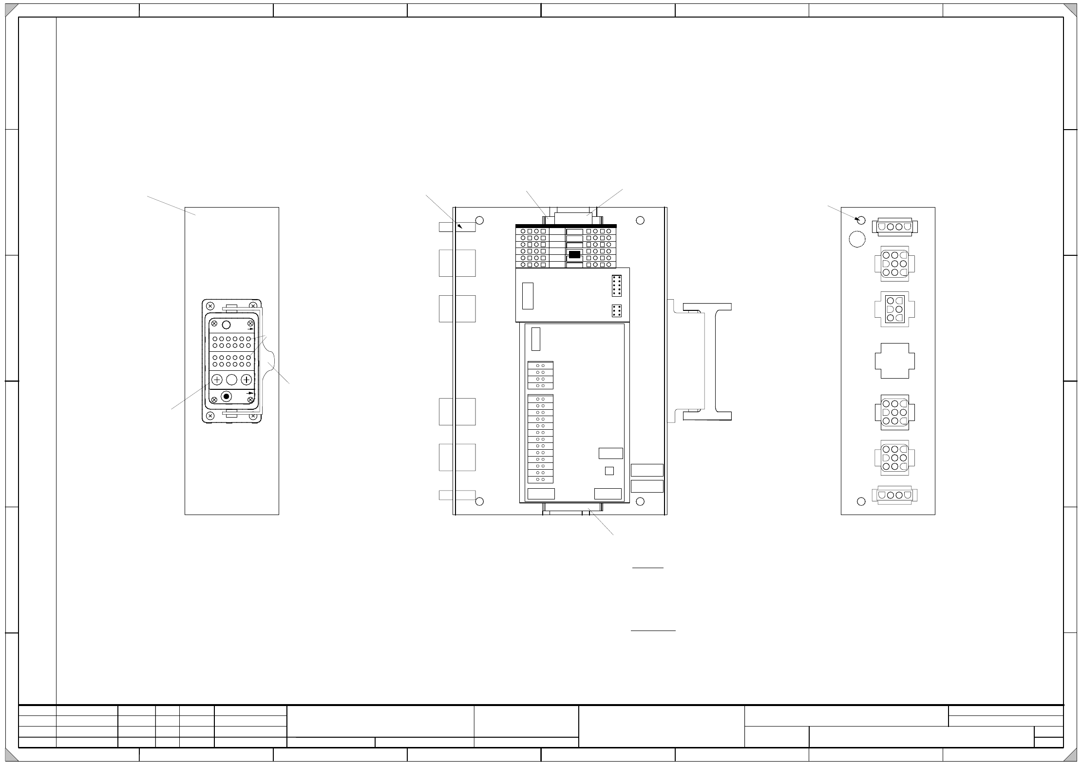
* Hinweis
Folgende Etiketten muessen aufgeklebt werden :
A: Identifikationsschild
B: Pruefschild
C: Erdungsschild ( GNYE )
* Please note
Fit the following labels:
A: identification label
B: inspection label
C: ground label ( GNYE )
A
B
Erdungsloch
Ground hole
Teil 001
Part 001
Steckerbeschriftung auf der Kante
Schriftgrösse 4mm
Connector label on the edge
Font size: 4mm
Teil 002
Part 002
Teil 003
Part 003
4
5
6
1
2
3
X100
Teil 002
Part 002
X3qc X4qc
X6qc
X5qc
13 26
12 25
11 24
10 23
9 22
8 21
7 20
6 19
5 18
4 17
3 16
2 15
1 14
4
3
2
1
8
7
6
5
X1qc
X2qc
F1
A1
(qc)
A2
(qd)
X3af
X4af
X6af
X21af
1
2
3
Pin1
A
C
B
Pneumatikmodul
(Kontakt bei 1 und 3)
Pneumatic module
(Contact at 1 and 3)
Modul
Module
A
C
Bügel
Bracket
X1af
X5af
X25af
X3af
X4af
X6af
X21af
X5af
X25af
X1af
1
1
10
6
X
1
q
d
X
2
q
d
X
3
q
d
C