D4+circuit(2006).pdf - 第34页
2 - ii SIPLAC E D4 De tai led Ci rcuit D iagra ms Fold er 12/2006 US Editi on TS-0101 01LD3 Temperature s ensor, head, gantr ies 1 - 4 2 - 41 LPET-01 0102LD3 PCB sing le co nveyor /PCB dual conv eyor, trac k 1, co nvey o…
SIPLACE D4 Detailed Circuit Diagrams Folder
12/2006 US Edition
2 - i
2 Detailed circuit diagrams
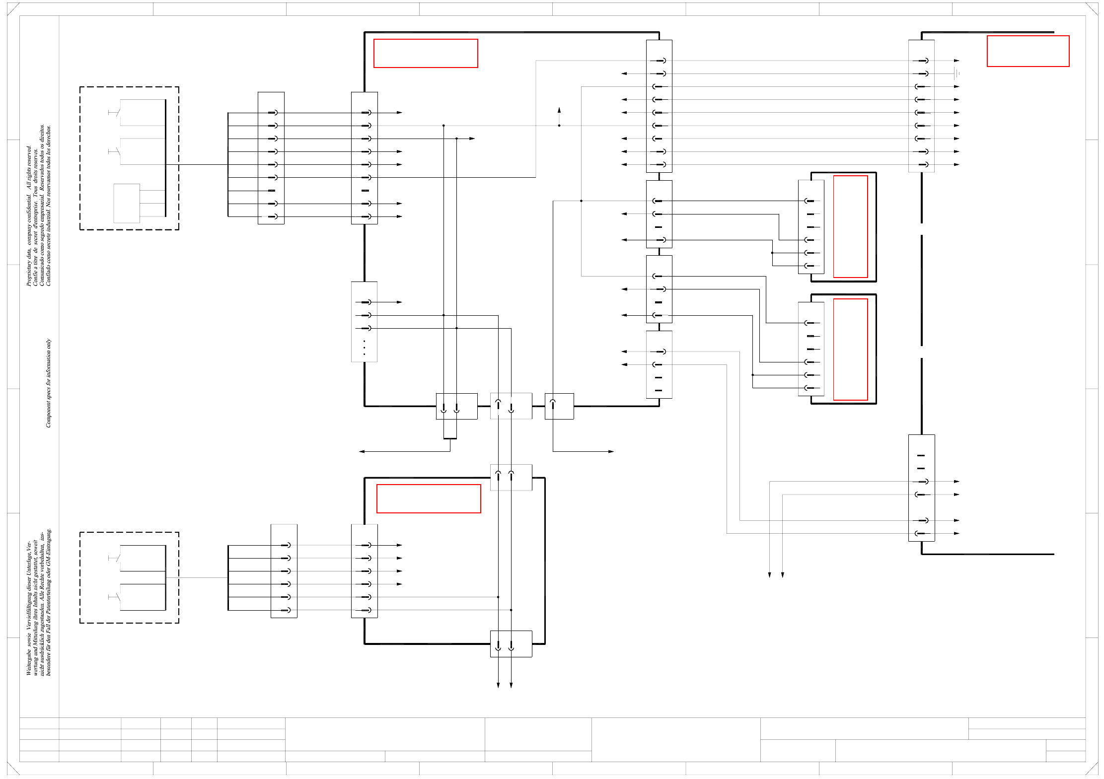
NH-010101LD3 Emergency-stop loop, START, STOP button (sh. 1 of 4) 2 - 1
NH-010101LD3 Emergency-stop loop, START, STOP button (sh. 2 of 4) 2 - 2
NH-010101LD3 Emergency-stop loop, START, STOP button (sh. 3 of 4) 2 - 3
NH-010101LD3 Emergency-stop loop, emergency-stop button, protective switch (sh. 4 of 4) 2 - 4
X01-020101LD3 X axis, gantry 1 (sh. 1 of 2) 2 - 5
X01-020101LD3 X axis, gantry 1 (sh. 2 of 2) 2 - 6
Y01-020101LD3 Y axis, gantry 1 (sh. 1 of 2) 2 - 7
Y01-020101LD3 Y axis, gantry 1 (sh. 2 of 2) 2 - 8
DR01-010102LD3 Star axis, 12-segment Collect&Place head, gantry 1 2 - 9
Z01-010102LD3 Z axis, 12-segment Collect&Place head, gantry 1 2 - 10
DP01-010102LD3 DP axis, 12-segment Collect&Place head, gantry 1 2 - 11
ZM01-010102LD3 Adjustment drive units, forced air,
12-segment Collect&Place head, gantry 1 2 - 12
X02-020101LD3 X axis, gantry 2 (sh. 1 of 2) 2 - 13
X02-020101LD3 X axis, gantry 2 (sh. 2 of 2) 2 - 14
Y02-020101LD3 Y axis, gantry 2 (sh. 1 of 2) 2 - 15
Y02-020101LD3 Y axis, gantry 2 (sh. 2 of 2) 2 - 16
DR02-010102LD3 Star axis, 12-segment Collect&Place head, gantry 2 2 - 17
Z02-010102LD3 Z axis, 12-segment Collect&Place head, gantry 2 2 - 18
DP02-010102LD3 DP axis, 12-segment Collect&Place head, gantry 2 2 - 19
ZM02-010102LD3 Adjustment drive units, forced air,
12-segment Collect&Place head, gantry 2 2 - 20
X03-020101LD3 X axis, gantry 3 (sh. 1 of 2) 2 - 21
X03-020101LD3 X axis, gantry 3 (sh. 2 of 2) 2 - 22
Y03-020101LD3 Y axis, gantry 3 (sh. 1 of 2) 2 - 23
Y03-020101LD3 Y axis, gantry 3 (sh. 2 of 2) 2 - 24
DR03-010102LD3 Star axis, 12-segment Collect&Place head, gantry 3 2 - 25
Z03-010102LD3 Z axis, 12-segment Collect&Place head, gantry 3 2 - 26
DP03-010102LD3 DP axis, 12-segment Collect&Place head, gantry 3 2 - 27
ZM03-010102LD3 Adjustment drive units, forced air,
12-segment Collect&Place head, gantry 3 2 - 28
X04-020101LD3 X axis, gantry 4 (sh. 1 of 2) 2 - 29
X04-010102LD3 X axis, gantry 4 (sh. 2 of 2) 2 - 30
Y04-020101LD3 Y axis, gantry 4 (sh. 1 of 2) 2 - 31
Y04-020101LD3 Y axis, gantry 4 (sh. 2 of 2) 2 - 32
DR04-010102LD3 Star axis, 12-segment Collect&Place head, gantry 4 2 - 33
Z04-010102LD3 Z axis, 12-segment Collect&Place head, gantry 4 2 - 34
DP04-010102LD3 DP axis, 12-segment Collect&Place head, gantry 4 2 - 35
ZM04-010102LD3 Adjustment drive units, forced air,
12-segment Collect&Place head, gantry 4 2 - 36
BEW-010101LD3 Interface, component trolley 2 - 37
GS-010101LD3 Tape cutter, distributor, sector 4
gantry 1 and gantry 4 (sh. 1 of 2) 2 - 38
GS-010101LD3 Tape cutter, distributor, sector 2
gantry 2 and gantry 3 (sh. 2 of 2) 2 - 39
PW-010101LD3 Nozzle changer 2 - 40
2 - ii
SIPLACE D4 Detailed Circuit Diagrams Folder
12/2006 US Edition
TS-010101LD3 Temperature sensor, head, gantries 1 - 4 2 - 41
LPET-010102LD3 PCB single conveyor/PCB dual conveyor, track 1,
conveyor control TSP 301 (sh. 1 of 10) 2 - 42
LPET-010102LD3 PCB single conveyor/PCB dual conveyor, track 1,
conveyor control TSP 301 (sh. 2 of 10) 2 - 43
LPET-010102LD3 PCB single conveyor/PCB dual conveyor, track 1,
conveyor control TSP 301 (sh. 3 of 10) 2 - 44
LPET-010102LD3 PCB single conveyor/PCB dual conveyor, track 1,
conveyor control TSP 301 (sh. 4 of 10) 2 - 45
LPET-010102LD3 PCB single conveyor/PCB dual conveyor, track 1,
conveyor control TSP 301 (sh. 5 of 10) 2 - 46
LPET-010102LD3 PCB single conveyor/PCB dual conveyor, track 1, conversion board
"conveyor rail A“, stationary conveyor side on the right (sh. 6 of 10) 2 - 47
LPET-010102LD3 PCB single conveyor/PCB dual conveyor, track 1, conversion board
"conveyor rail B“, stationary conveyor side on the right (sh. 7 of 10) 2 - 48
LPET-010102LD3 PCB single conveyor/PCB dual conveyor, track 1, conversion board
"conveyor rail A“, stationary conveyor side on the left (sh. 8 of 10) 2 - 49
LPET-010102LD3 PCB single conveyor, conversion board "conveyor rail B“,
stationary conveyor side on the left (sh. 9 of 10) 2 - 50
LPET-010102LD3 PCB single conveyor/PCB dual conveyor, track 1, conversion board
lifting table, placement areas 1 + 2 (sh. 10 of 10) 2 - 51
LPDT-010102LD3 PCB dual conveyor, track 2, conveyor control TSP 301E (sh. 1 of 8) 2 - 52
LPDT-010102LD3 PCB dual conveyor, track 2, conveyor control TSP 301E (sh. 2 of 8) 2 - 53
LPDT-010102LD3 PCB dual conveyor, track 2, conveyor control TSP 301E (sh. 3 of 8) 2 - 54
LPDT-010102LD3 PCB dual conveyor, track 2, conveyor control TSP 301E (sh. 4 of 8) 2 - 55
LPDT-010102LD3 PCB dual conveyor, track 2, conveyor control TSP 301E (sh. 5 of 8) 2 - 56
LPDT-010102LD3 PCB dual conveyor, track 2, conversion board "conveyor rail C“ (sh. 6 of 8) 2 - 57
LPDT-010102LD3 PCB dual conveyor, track 2, conversion board "conveyor rail D“ (sh. 7 of 8) 2 - 58
LPDT-010102LD3 PCB dual conveyor, track 2, conversion board "lifting table“,
placement areas 1 + 2 (sh. 8 of 8) 2 - 59
2 - 1
2 Detailed circuit diagrams
NH-010101LD3 Emergency-stop loop, START, STOP button (sh. 1 of 4)
BK
4-pole
X15df
1
6
9
7
8
2
4
5
3
X22df
1
BK
BK
X400:2D
X400:33D
X400:31D
X400:28D
X400:29C
X400:30C
GND
X400:26C
X11df
1
2
3
4
GND
X400:60
X400:10C
+5V
n.u.
BK
X14df
1
2
3
4
n.u.
BK
n.u.
n.u.
X400:10B
+5V
X400:5B
4
X9df
2
3
1
X23df:1
X23df:2
n.u.
n.u.
03032394
OG
BK
BK
1
3
2
X4cf
X3cf
5
7
GY
BU
5
6
4 BK
BK
BK
00335306
PCB output, left
StopStart
S1
433
S2
4
WH (W1)
n.u.
1 (W1)
2 (W1)
1 (W2)
2 (W2)
PCC 44
PCC 43
PCC 34
PCC 33
n.u.
n.u.
n.u.
n.u.
PCC 43
PCC 44
1 (W1)
2 (W1)
03032366-W2
03032366 - W1
X9bf:1
To sheet 2 To sheet 2
X9bf:2
n.u.
BK
BK
BN
BN
WH
WH
BK
GNYE
BK
BK
BK
BK
BK
PK
WH
PK
WH
BK
BK
WH
8
7
6
5
9
8
7
6
5
2
3
1
X10df
2
3
1
X86
03032399
(W1)
(W1)
(W1)
(W1)
(W2)
(W2)
(W1)
(W1)
GY
PK+BU
n.u.
n.u.
n.u.
n.u.
YE
GN
WH+BN
03032455
BU
RD
GN+YE
n.u.
WH+BN
PK
GY
YE
WH+BN+GN
GN
WH
BN
YE
BU
PK
GY
RST
COM
HS
43 43
StopStart
S1
S2
CO counter
Distributor sector 4 (main)
03032354 (df)
OG
BK
BK
BK
BK
BK
n.u.
BK
WH
X400:17C
X400:32C
X400:20C
X7qb:5
X400:4D
GND
5
6
X4df
1
n.u.
n.u.
BK
OG
X5df:1
BK
6-pole
+24V
GY
BU
5
X6df
7
9-pole
03032396
S_StartButton
S_StopButton
X15df:3
X400:16C
X3df
GY5
BU7BK
BK
5
7
X6cf
BK
=
Date
Check.
Stand.
Author
Sheet
Orig. Repl. f. Repl. byNameDateModifiedStatus
Sh.
+
2
F
3
F
8
A
2
D
3
C
B
A
5
B
41
E
5
41
C
D
E
Emerg. stop loop
Function st.
678
76
1.
1.
1.
08.05.06
08.05.06
08.05.06
08.05.2006
Hi
NH01-010101LD3
1
4
Hi
Hi
Hi
Copyright reserved
Product st.
Document st.
SIPLACE D4
CAD file : NH01-010101LD3_SH01.DWG
START, STOP button
SIEMENS AG
4 4
9
GN
BN
(W1)
(W1)
YE (W1)
PK
BU
WH+BN
GN
GY
YE
03032414 - W1
6
5
3
4
X84
2
1
GN (W1)
YE (W1)
+ WH (W1)
YE (W2)
WH (W2)
GN (W2)
BN (W1+W2)
X300:5A
X3cf:1
X3cf:4, X6cf:4
X3cf:2
S_StartButton
S_StopButton
To sheet 2
X3af
03032353 (cf)
Distributor sector 3
To sheet 2
X6bf:5
To sheet 2
X6bf:7
03032404
03032390
To sheet 2
X12bf:1
Power supply side
8
9
X12
6
7
5
4
1
2
3
WH+BN
GNYE
1
3
2
GN+YE
GY
PK
BU
(W1)
(W1)
(W1)
(W1)
(W2)
(W2)
(W1)
(W2)
(W2)
4P40V
RGP
S_Ready
S_ControlOn
OnButton
Ctrl_On
EmergStop_End
EmergStop_Begin
Ctrl_TapeCutter
Power supply
03039618
To sheet 3
X2ah
2
1
4
3
6
5
6
1
3
5
4
2
X2dh
Gantry 1
Tape cutter
00329699 (ah)
Tape cutter
Gantry 4
00329699 (dh)
YE
GN
Key
Key
YE
Key
GN
Key
GN+YE
BN
WH
WH
BN
GN+YE
03032384
03032383
03032365
2
4
6
5
3
X13
1
To sheet 3
n.u.
S
ee page 3-9
S
ee page 3-7
S
ee page 3-17
S
ee page 5-2
S
ee page 5-2