D4+circuit(2006).pdf - 第33页
SIPLACE D4 Deta iled Circu it Diagra ms Folder 12/2006 US Edit ion 2 - i 2 Detailed circuit diag rams NH-01010 1LD3 Emergency-st op loop, START , STOP bu tton (sh. 1 of 4) 2 - 1 NH-01010 1LD3 Emergency-st op loop, START …
1 - 19
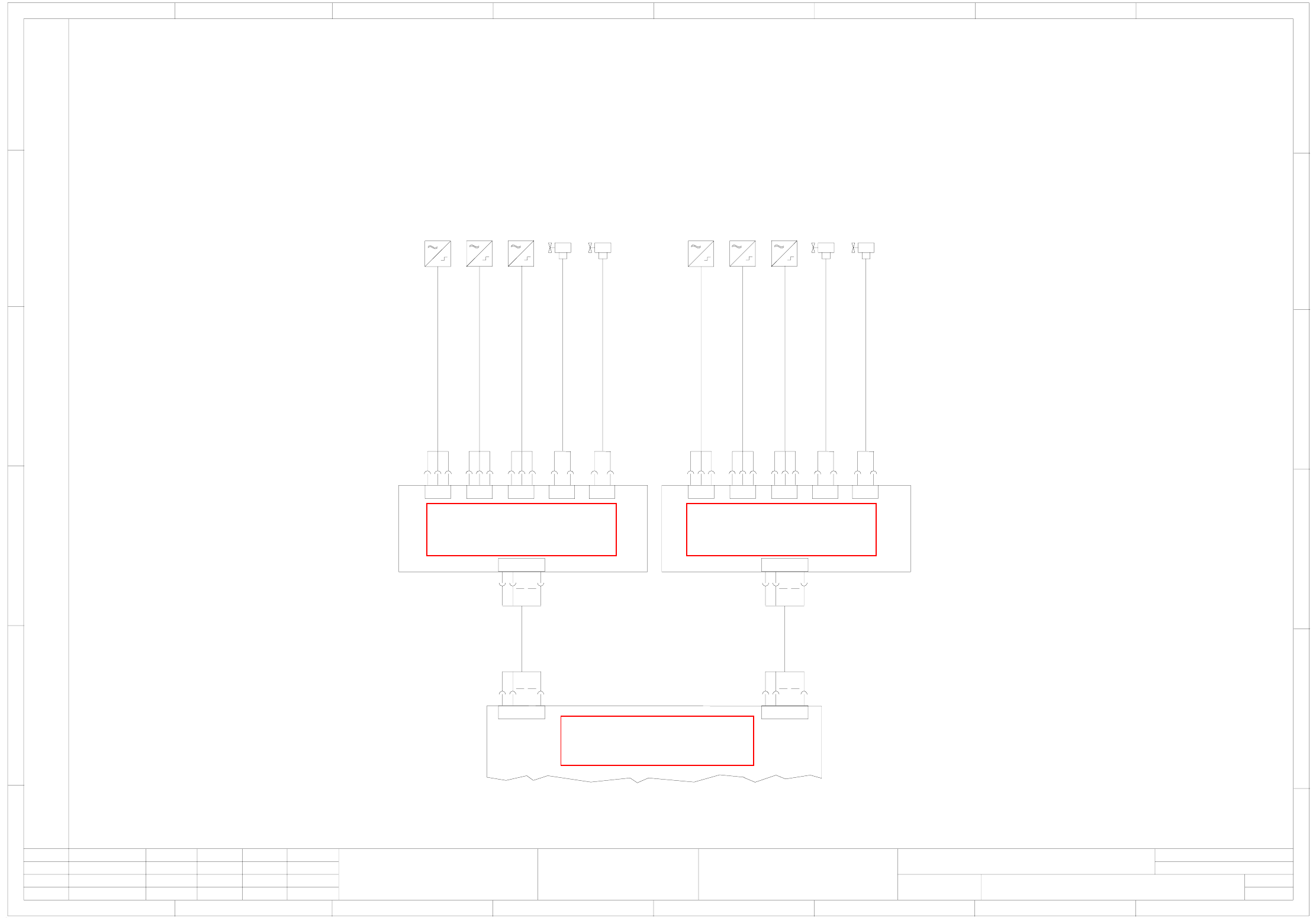
03040748-010101LD3 Single conveyor (sh. 5 of 5)
Weitergabe sowie Vervielfältigung dieser Unterlage, Verwertung und
Mitteilung ihres Inhalts nicht gestattet, soweit nicht ausdrücklich zugestanden.
Zuwiderhandlungen verpflichten zu Schadenersatz. Alle Rechte vorbehalten,
insbesondere für den Fall der Patenterteilung oder GM-Eintragung.
Proprietary data, company confidential. All rights reserved.
Confie a titre de secret d'entreprise. Tous droits reserves.
Confiado como secrete industrial. Nos reservamos todos los derechos.
Comunicado como segredo empresarial. Reservados todos os direitos.
Stand.
Check.
Author
Date
Status Modified Date Name
Raabe
25.05.05
Copyright reserved
SIEMENS AG
03040748-010101LD3
Single conveyor
SIPLACE D4
5
Sheet
Sh.
5
2
10
1
2
10
X2kt
00363111-xx
Cable: incremental encoder, track B (long)
Limit switch, lifting table
Cable: incremental encoder, track A (long)
Cable: lifting table valve down
Cable: lifting table valve up
00363113-xx
00363076-xx
03048851-xx
03048852-xx
00363111-xx
Cable: incremental encoder, track B (long)
Limit switch, lifting table
Cable: incremental encoder, track A (long)
Cable: lifting table valve down
Cable: lifting table valve up
00363113-xx
00363076-xx
03048851-xx
03048852-xx
00359425-xx
Conversion board, assembly tray
(kt)
00363438-xx
00363439-xx
67 8
1234567 8
A
B
C
D
E
F
Lifting table conversion board (placement area 1)
X6
00362766-xx
Incremental encoder, track A, lifting table
Incremental encoder, track B, lifting table
(upper fork light barrier)
(lower fork light barrier)
Cylinder switch, lifting table
Lifting table, valve up (connection "14")
Lifting table, valve down (connection "12")
X1 X2
Lifting table, placement area 1
(lv)
2
3
6
P24
GND
IN
A
B
C
D
E
F
12345
2
3
6
P24
GND
IN
X3 X4 X5
2
6
GND
OUT
2
6
GND
OUT
2
3
6
P24
GND
IN
X6lv
X1kt
1
2
10
1
2
10
X1kt
Lifting table conversion board (placement area 2)
X6
00362766-xx
Incremental encoder, track A, lifting table
Incremental encoder, track B, lifting table
(upper fork light barrier)
(lower fork light barrier)
Cylinder switch, lifting table
Lifting table, valve up (connection "14")
Lifting table, valve down (connection "12")
X1 X2
Lifting table, placement area 2
(lw)
2
3
6
P24
GND
IN
2
3
6
P24
GND
IN
X3 X4 X5
2
6
GND
OUT
2
6
GND
OUT
2
3
6
P24
GND
IN
X6lw
X2kt
1
S
ee page 2-51
S
ee page 2-51
See page 2-44
SIPLACE D4 Detailed Circuit Diagrams Folder
12/2006 US Edition
2 - i
2 Detailed circuit diagrams
NH-010101LD3 Emergency-stop loop, START, STOP button (sh. 1 of 4) 2 - 1
NH-010101LD3 Emergency-stop loop, START, STOP button (sh. 2 of 4) 2 - 2
NH-010101LD3 Emergency-stop loop, START, STOP button (sh. 3 of 4) 2 - 3
NH-010101LD3 Emergency-stop loop, emergency-stop button, protective switch (sh. 4 of 4) 2 - 4
X01-020101LD3 X axis, gantry 1 (sh. 1 of 2) 2 - 5
X01-020101LD3 X axis, gantry 1 (sh. 2 of 2) 2 - 6
Y01-020101LD3 Y axis, gantry 1 (sh. 1 of 2) 2 - 7
Y01-020101LD3 Y axis, gantry 1 (sh. 2 of 2) 2 - 8
DR01-010102LD3 Star axis, 12-segment Collect&Place head, gantry 1 2 - 9
Z01-010102LD3 Z axis, 12-segment Collect&Place head, gantry 1 2 - 10
DP01-010102LD3 DP axis, 12-segment Collect&Place head, gantry 1 2 - 11
ZM01-010102LD3 Adjustment drive units, forced air,
12-segment Collect&Place head, gantry 1 2 - 12
X02-020101LD3 X axis, gantry 2 (sh. 1 of 2) 2 - 13
X02-020101LD3 X axis, gantry 2 (sh. 2 of 2) 2 - 14
Y02-020101LD3 Y axis, gantry 2 (sh. 1 of 2) 2 - 15
Y02-020101LD3 Y axis, gantry 2 (sh. 2 of 2) 2 - 16
DR02-010102LD3 Star axis, 12-segment Collect&Place head, gantry 2 2 - 17
Z02-010102LD3 Z axis, 12-segment Collect&Place head, gantry 2 2 - 18
DP02-010102LD3 DP axis, 12-segment Collect&Place head, gantry 2 2 - 19
ZM02-010102LD3 Adjustment drive units, forced air,
12-segment Collect&Place head, gantry 2 2 - 20
X03-020101LD3 X axis, gantry 3 (sh. 1 of 2) 2 - 21
X03-020101LD3 X axis, gantry 3 (sh. 2 of 2) 2 - 22
Y03-020101LD3 Y axis, gantry 3 (sh. 1 of 2) 2 - 23
Y03-020101LD3 Y axis, gantry 3 (sh. 2 of 2) 2 - 24
DR03-010102LD3 Star axis, 12-segment Collect&Place head, gantry 3 2 - 25
Z03-010102LD3 Z axis, 12-segment Collect&Place head, gantry 3 2 - 26
DP03-010102LD3 DP axis, 12-segment Collect&Place head, gantry 3 2 - 27
ZM03-010102LD3 Adjustment drive units, forced air,
12-segment Collect&Place head, gantry 3 2 - 28
X04-020101LD3 X axis, gantry 4 (sh. 1 of 2) 2 - 29
X04-010102LD3 X axis, gantry 4 (sh. 2 of 2) 2 - 30
Y04-020101LD3 Y axis, gantry 4 (sh. 1 of 2) 2 - 31
Y04-020101LD3 Y axis, gantry 4 (sh. 2 of 2) 2 - 32
DR04-010102LD3 Star axis, 12-segment Collect&Place head, gantry 4 2 - 33
Z04-010102LD3 Z axis, 12-segment Collect&Place head, gantry 4 2 - 34
DP04-010102LD3 DP axis, 12-segment Collect&Place head, gantry 4 2 - 35
ZM04-010102LD3 Adjustment drive units, forced air,
12-segment Collect&Place head, gantry 4 2 - 36
BEW-010101LD3 Interface, component trolley 2 - 37
GS-010101LD3 Tape cutter, distributor, sector 4
gantry 1 and gantry 4 (sh. 1 of 2) 2 - 38
GS-010101LD3 Tape cutter, distributor, sector 2
gantry 2 and gantry 3 (sh. 2 of 2) 2 - 39
PW-010101LD3 Nozzle changer 2 - 40
2 - ii
SIPLACE D4 Detailed Circuit Diagrams Folder
12/2006 US Edition
TS-010101LD3 Temperature sensor, head, gantries 1 - 4 2 - 41
LPET-010102LD3 PCB single conveyor/PCB dual conveyor, track 1,
conveyor control TSP 301 (sh. 1 of 10) 2 - 42
LPET-010102LD3 PCB single conveyor/PCB dual conveyor, track 1,
conveyor control TSP 301 (sh. 2 of 10) 2 - 43
LPET-010102LD3 PCB single conveyor/PCB dual conveyor, track 1,
conveyor control TSP 301 (sh. 3 of 10) 2 - 44
LPET-010102LD3 PCB single conveyor/PCB dual conveyor, track 1,
conveyor control TSP 301 (sh. 4 of 10) 2 - 45
LPET-010102LD3 PCB single conveyor/PCB dual conveyor, track 1,
conveyor control TSP 301 (sh. 5 of 10) 2 - 46
LPET-010102LD3 PCB single conveyor/PCB dual conveyor, track 1, conversion board
"conveyor rail A“, stationary conveyor side on the right (sh. 6 of 10) 2 - 47
LPET-010102LD3 PCB single conveyor/PCB dual conveyor, track 1, conversion board
"conveyor rail B“, stationary conveyor side on the right (sh. 7 of 10) 2 - 48
LPET-010102LD3 PCB single conveyor/PCB dual conveyor, track 1, conversion board
"conveyor rail A“, stationary conveyor side on the left (sh. 8 of 10) 2 - 49
LPET-010102LD3 PCB single conveyor, conversion board "conveyor rail B“,
stationary conveyor side on the left (sh. 9 of 10) 2 - 50
LPET-010102LD3 PCB single conveyor/PCB dual conveyor, track 1, conversion board
lifting table, placement areas 1 + 2 (sh. 10 of 10) 2 - 51
LPDT-010102LD3 PCB dual conveyor, track 2, conveyor control TSP 301E (sh. 1 of 8) 2 - 52
LPDT-010102LD3 PCB dual conveyor, track 2, conveyor control TSP 301E (sh. 2 of 8) 2 - 53
LPDT-010102LD3 PCB dual conveyor, track 2, conveyor control TSP 301E (sh. 3 of 8) 2 - 54
LPDT-010102LD3 PCB dual conveyor, track 2, conveyor control TSP 301E (sh. 4 of 8) 2 - 55
LPDT-010102LD3 PCB dual conveyor, track 2, conveyor control TSP 301E (sh. 5 of 8) 2 - 56
LPDT-010102LD3 PCB dual conveyor, track 2, conversion board "conveyor rail C“ (sh. 6 of 8) 2 - 57
LPDT-010102LD3 PCB dual conveyor, track 2, conversion board "conveyor rail D“ (sh. 7 of 8) 2 - 58
LPDT-010102LD3 PCB dual conveyor, track 2, conversion board "lifting table“,
placement areas 1 + 2 (sh. 8 of 8) 2 - 59