D4+circuit(2006).pdf - 第169页
SIPLACE D4 Deta iled Circu it Diagra ms Folder 12/2006 US Edit ion 6 - i 6 Pneumatic diagrams 00324065 -0408 01XD3 S IPLAC E pneumati c tape cutter 6 - 1 00329906 -0101 01ED3 Pneu matic s ymbols 6 - 2 03028843 -0201 01ND…
5 - 38
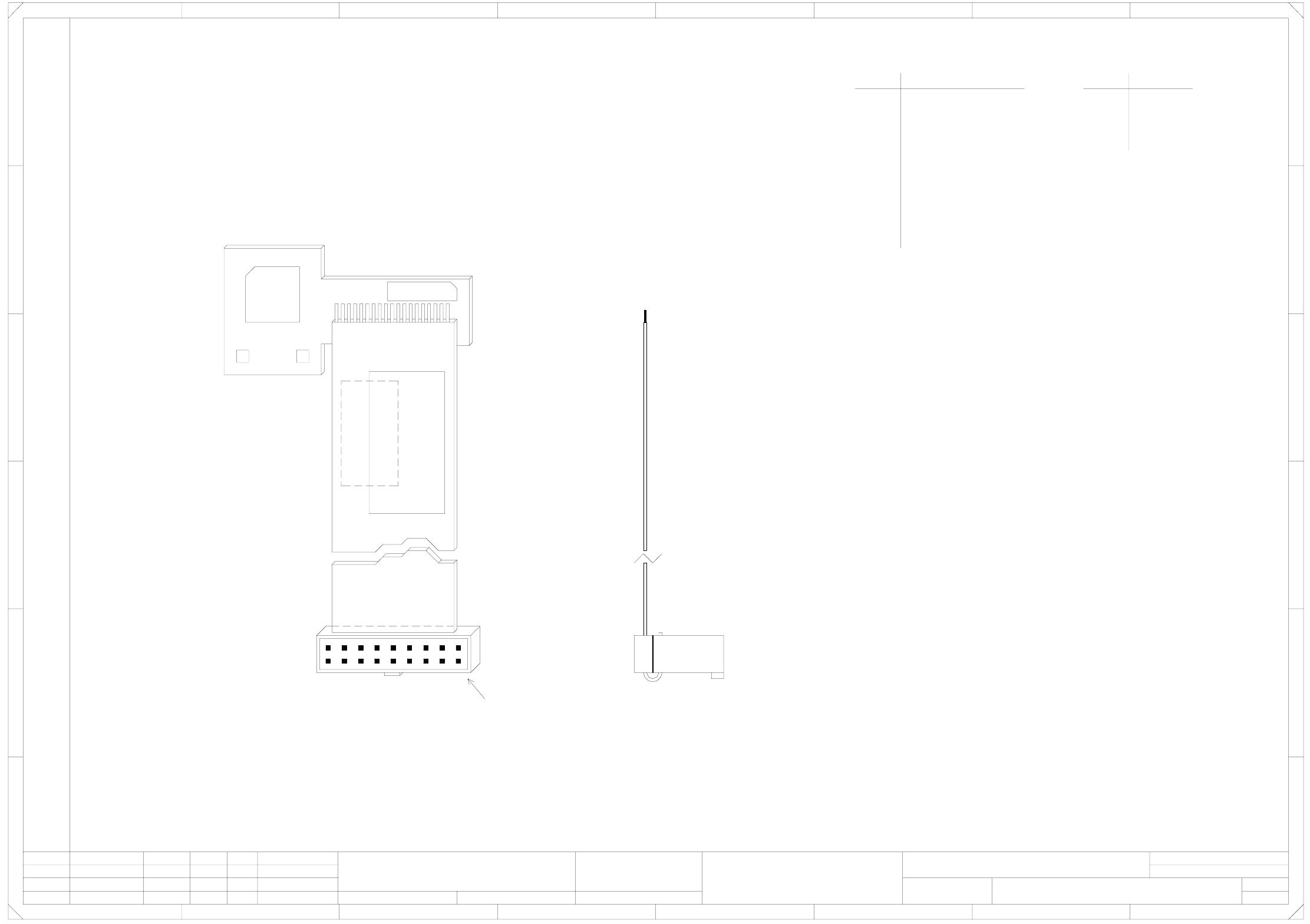
03048125-010101ND4 Adjustment drive unit, DP axis (sh. 2 of 2)
Bauteilangaben nur zur Information
Weitergabe sowie Vervielfaeltigung dieser Unterlage, Ver-
wertung und Mitteilung ihres Inhalts nicht gestattet, soweit
nicht ausdruecklich zugestanden. Alle Rechte vorbehalten, ins-
besondere fuer den Fall der Patenterteilung oder GM-Eintragung.
2.
1.
1.
F
1
Doc. status
Product status
Function status
E
D
23
07.02.2006
4
Comunicado como segredo empresarial. Reservados todos os direitos.
Confie a titre de secret d'entreprise. Tous droits reserves.
Proprietary data , company confidential . All rights reserved.
Confiado como secrete industrial. Nos reservamos todos los derechos.
C
B
A
1234
SIPLACE D4
03048125-010102ND4
5678
2
+
=
2
F
E
D
567
C
B
8
A
Status Modified NameDate Stand. Orig. Replacement for Replaced by
Date
Author
Check.
Sheet
Sh.
4
9
10
8
7
6
5
X1
2
3
11
4
2
3
X3
B1 motor
A2 motor
B2 motor
A1 motor
AGND
LED output signal
+ 15 V
+ 5 V
GND
A1-motor
A2-motor
B1-motor
AGND
B2-motor
SIEMENS AG
Copyright reserved
J. Krüger, BMK
X1
X3
A
B
V1
H1 H2
Pin 1
Turning station
Adjustment unit
6 - ii
SIPLACE D4 Detailed Circuit Diagrams Folder
12/2006 US Edition