D4+circuit(2006).pdf - 第73页
2 - 39 GS-010 101LD3 T ape cu tter, distributor, sector 2 gantry 2 a nd ga ntry 3 ( sh. 2 o f 2) Modified Status Date CAD file : GS-010101L D3_SH02.DWG Orig./Repl. f./Repl. by Stand. Nam e Check. Stromlaufplan/Circuit di…
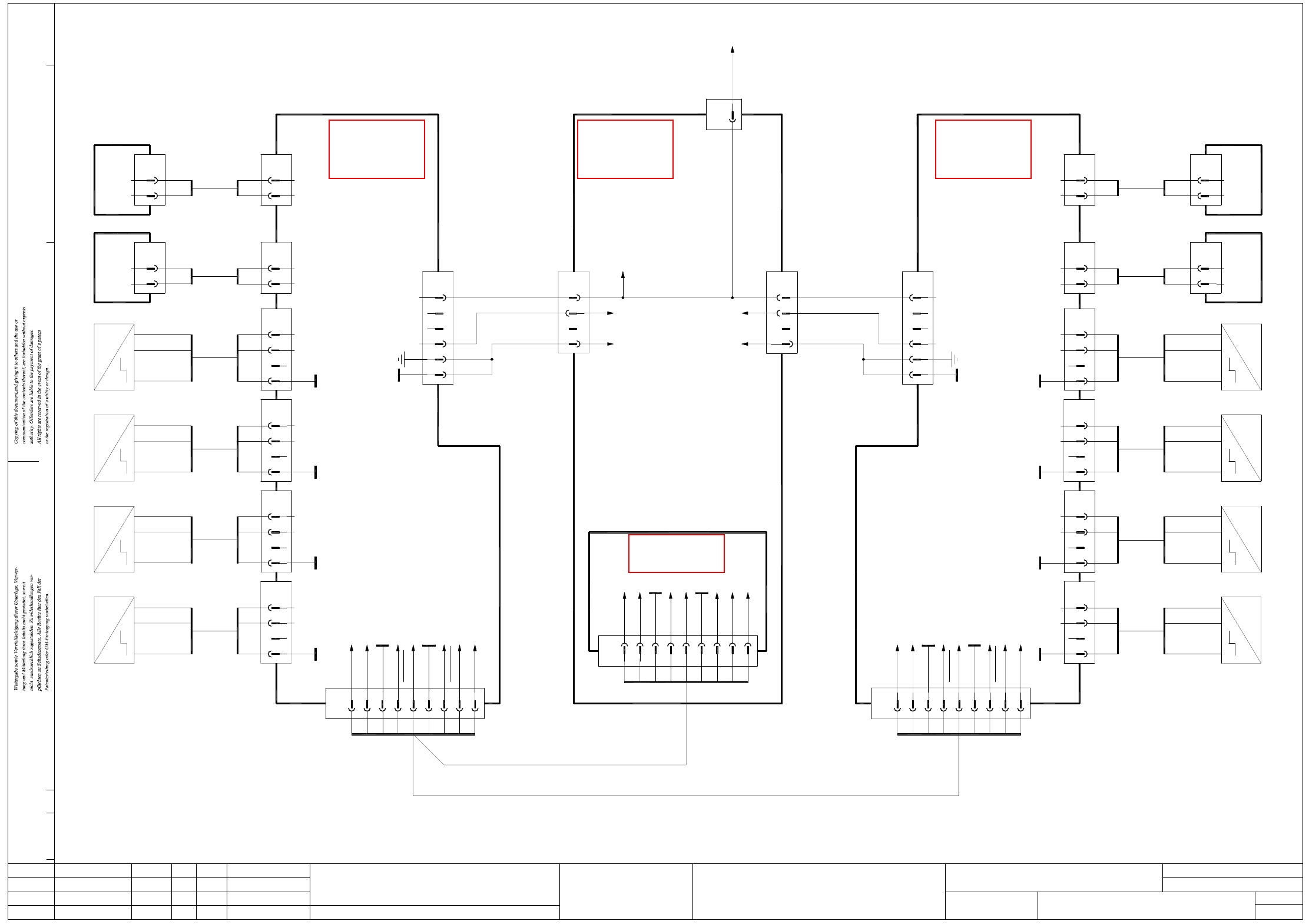
2 - 38
GS-010101LD3 Tape cutter, distributor, sector 4
gantry 1 and gantry 4 (sh. 1 of 2)
CANL
9-pole
S4
+5V
GND
Key
X5ah
Valve
0V
GND
+5V
+30V switchable
YE
GN
BN
Key
Key
WH
X4ah
5
GND
6
n.u.
n.u.
3
4
2
1
9
7
8
CANH
GND
n.u.
CAN_Reset
CAN_INT
3
2
BK
BN
BK
Tape cutter
Gantry 1
00329699 (ah)
X2ah
5
6
3
4
2
1
Hi1.
Hi1.
GS-010101LD3
08.05.06
08.05.06
08.05.06
08.05.2006
Copyright reserved
SIEMENS AG
X10ah
5
6
ModifiedStatus Date
CAD file : GS-010101LD3_SH01.DWG
Orig./Repl. f./Repl. byStand.Name
Check.
Stromlaufplan/Circuit diagram
Mat. no. :
Author Hi
Date
Sh.
Sh.
SIPLACE D4
1
2
Tape cutter
Document st.
Product st.
Function st.
1. Hi
5
2
RD
BK
1
2
00332894
BN
BU
BK Output
-
+
~
~
Right sensor
Piston extended
RD
BK
00332896
Signal
0V
Extend left piston
Valve
GND
Key
S3
BK6
5
3 BK
+5V
X9ah
2 BN
BK
BU
00332894
Output
-
BN +
Piston retracted
~
~
Right sensor Left sensor
Piston extended
5
GND
Key
6
BK BK Output
S2
+5V
3
2
BK
BN
X8ah
BN
BU
00332894
-
+
~
~
BK6GND
Key
S1
+5V
BK3
5
2
X7ah
BN
OutputBK
BU
BN
00332894
-
+
Piston retracted
~
~
Left sensor
BK2
0V
Valve
5 RD
X6ah
1BK
RD
00334380
2
0V
Valve
Extend right piston
Signal
~
~
Tape cutter
00329699 (dh)
Gantry 4
4
6
5
3
2
X2dh
1
+30V switchable
+5V
GND
9-poleX4dh
CANH7
CANL
CAN_INT
GND
n.u.
n.u.
GND
4
2
1
3
5
6
CAN_Reset
n.u.
8
9
00332896
00332894
X5dh
X7dh
Left sensor
Piston retracted
Valve
Extend left piston
1
2
0V
Signal
RD
BK
BN
BU
BKOutput
-
+BN
BK
BK
RD
BK 2
5
2
3
5
6
Valve
0V
Key
+5V
S1
GND
BN
GN
YE
WH
Key
Key
Extend right piston
Valve
Signal
2
1
0V
BK
RD
00334380
X6dh
BK
RD
2
5
Valve
0V
~
Piston extended
Left sensor
Output BK
+
-
~
BU
BN
BK 6
5
00332894
BK
BN
3
2
GND
Key
+5V
S2
X8dh
+5V
~
Piston retracted
~
Right sensor
-
Output BK
BU
00332894
6BK
BK
5
3
GND
Key
S3
+BN BN
X9dh
2
~
Right sensor
Piston extended
+
Output
-
~
BK
BU
BN
X10dh
00332894
BK 6
5
BK
BN
3
2
S4
GND
Key
+5V
ADR1_1
CANL
ADR1_0
GND
n.u.
GND
3
X5qe
1
2
5
4
6
GND_ADR1
n.u.
CANH
8
7
9
CAN interface
03032346
03032412
03032412
X15df
1
4-pole
WH
03032390
To sheet 2
X12bf:1
4
3
WH
X14df
2
1
BK
PK
n.u.
4
3
GND
+5V
Ctrl_TapeCutter
X11df
2
1
03032354 (df)
Distributor sector 4
(main)
WH
PK
BK
X400:5B
X400:10B
X400:6D
X400:10C
X22df:3
GN+YEGND
n.u.
GN+YE
+5V
Ctrl_TapeCutter
03032384 03032383
Gantry 1 and gantry 4
Distributor sector 4
S
ee page 5-2
S
ee page 3-9
S
ee page 5-2
S
ee page 5-20
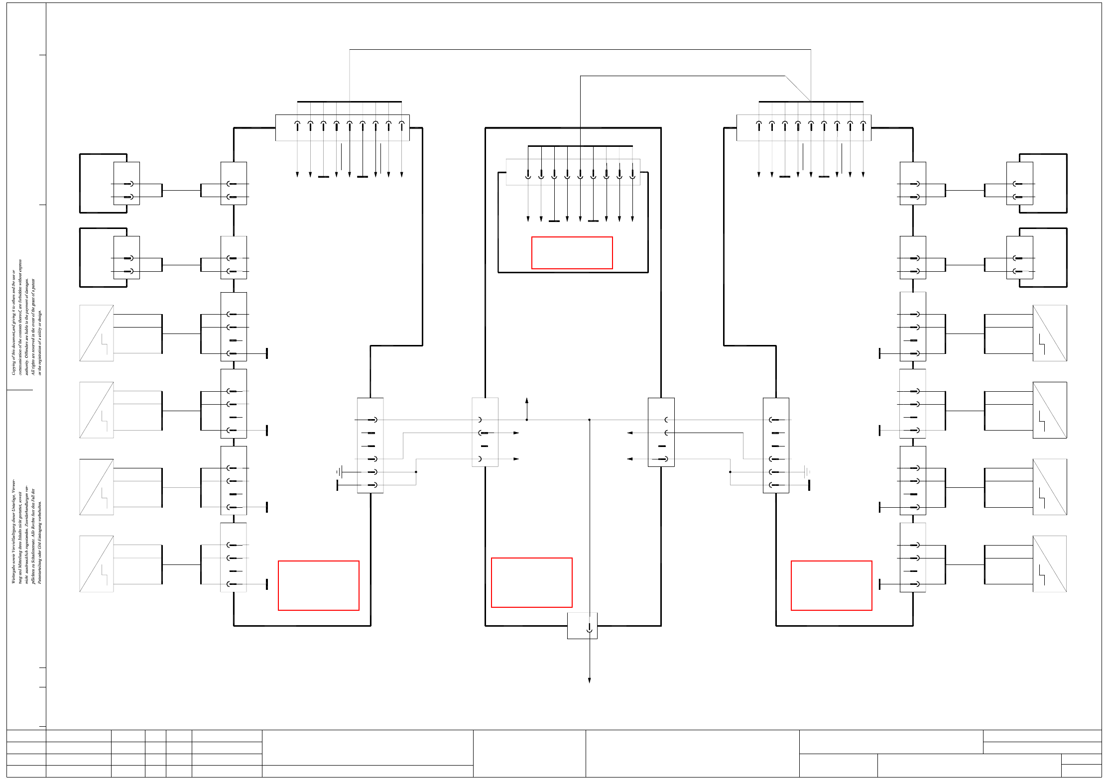
2 - 39
GS-010101LD3 Tape cutter, distributor, sector 2
gantry 2 and gantry 3 (sh. 2 of 2)
ModifiedStatus Date
CAD file : GS-010101LD3_SH02.DWG
Orig./Repl. f./Repl. byStand.Name
Check.
Stromlaufplan/Circuit diagram
Mat. no. :
Author Hi
Date
Sh.
Sh.
SIPLACE D4
2
2
Tape cutter
Document st.
Product st.
Function st.
1. Hi
Hi1.
Hi1.
~
Right sensor Left sensor
Piston extended
5
GND
Key
6
BK BK Output
S2
+5V
3
2
BK
BN
X8bh
BN
BU
00332894
-
+
~
~
BK6GND
Key
S1
+5V
BK3
5
2
X7bh
BN
OutputBK
BU
BN
00332894
-
+
Piston retracted
~
~
Left sensor
BK2
0V
Valve
5 RD
X6bh
1BK
RD
00334380
2
0V
Valve
Extend right piston
Signal
~
~
Tape cutter
00329699 (ch)
Gantry 3
4
6
5
3
2
X2ch
1
+30V switchable
+5V
GND
00332896
00332894
X5ch
X7ch
BN
BU
BK Output
-
+
~
~
Right sensor
Piston extended
RD
BK
00332896
Signal
0V
Extend left piston
Valve
GND
Key
S3
BK6
5
3 BK
+5V
X9bh
2 BN
BK
BU
00332894
Output
-
BN +
Piston retracted
~
BN
Key
Key
WH
S4
+5V
GND
Key
X5bh
Valve
0V
5
2
RD
BK
1
2
00332894
BK
BN
BK
Tape cutter
Gantry 2
00329699 (bh)
X2bh
5
6
3
4
2
1
GND
+5V
+30V switchable
YE
GN
GS-010101LD3
08.05.06
08.05.06
08.05.06
08.05.2006
Copyright reserved
SIEMENS AG
X10bh
5
6
3
2
Gantry 2 and gantry 3
Distributor sector 2
8CAN_Reset
n.u.
9-pole
1
X4ch
GND
n.u.
GND
CAN_INT
CANL
CANH
3
2
4
6
5
7
n.u. 9
9-pole
CANL
CAN_INT
GND
n.u.
n.u.
2
X4bh
1
3
4
5
CAN_Reset
n.u.
CANH
GND
7
6
8
9
CAN interface
ADR1_1 1
X5re
2
3GND
CANL
GND_ADR1
ADR1_0
5
4
6
n.u.
GND
8
7
9
n.u.
CANH
03032346
03032422
03032422
BK
Left sensor
Piston retracted
Valve
Extend left piston
1
2
0V
Signal
RD
BK
BN
BU
BKOutput
-
+BN
BK
BK
RD
BK 2
5
2
3
5
6
Valve
0V
Key
+5V
S1
GND
BN
GN
YE
WH
Key
Key
Extend right piston
Valve
Signal
2
1
0V
BK
RD
00334380
X6ch
BK
RD
2
5
Valve
0V
~
Piston extended
Left sensor
Output BK
+
-
~
BU
BN
BK 6
5
00332894
BK
BN
3
2
GND
Key
+5V
S2
X8ch
+5V
~
Piston retracted
~
Right sensor
-
Output BK
BU
00332894
6BK
BK
5
3
GND
Key
S3
+BN BN
X9ch
2
~
Right sensor
Piston extended
+
Output
-
~
BK
BU
BN
X10ch
00332894
BK 6
5
BK
BN
3
2
S4
GND
Key
+5V
X12bf
1
6-pole
WH
03032390
To sheet 1
X15df:1
4
3
WH
X14bf
2
1
BK
PK
n.u.
4
3
GND
+5V
Ctrl_TapeCutter
X11bf
2
1
03032352 (bf)
Distributor sector 2
(sub-)
WH
PK
BK
X200:8C
X200:10C
X200:8D
X200:10B
X2bf:1
GN+YEGND
n.u.
GN+YE
+5V
Ctrl_TapeCutter
03032406 03032405
S
ee page 5-2
S
ee page 3-3
S
ee page 5-2
S
ee page 5-20
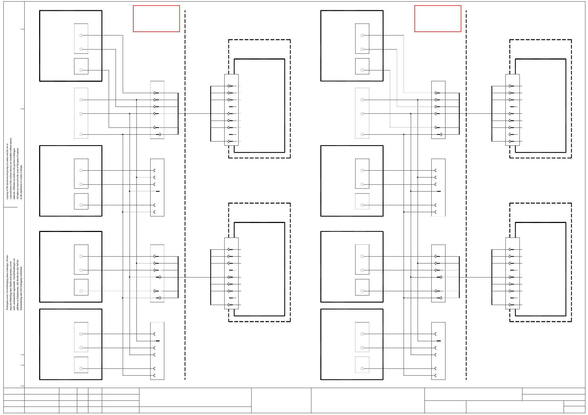
2 - 40
PW-010101LD3 Nozzle changer
BU
03032438
Control board
Nozzle changer
00317353 (ka)
Ctrl_ValveNC 1a
S_NCRight (closed)
S_NCLeft (open)
Ctrl_ValveNC 1b
BK3
X8qb
2BK
4BK
CAN I/O module 2
X3qb
X8qb
1 BK
S_NCRight (closed)
S_NCLeft (open)
CAN I/O module 2
1
2
X3qb
BK
4
1
2
X19df
WH
BN
GN
YE
GY
PK
6
5
Valve control
GND
+24V
1
NC open
3
4
2
spare
X1ka
9
8
7
GND
NC closed
YE
GN
GY
BN
WH
PK
00331653 (ka)
Location 4
Nozzle changer (4a)
4
3
X20df
2
1
5
6
OG
WH
n.u.
CAN I/O module 2
S_NCLeft (open)
S_NCRight (closed)
Ctrl_ValveNC 4a
BK6
X8qb
3BK
BK5
X3qb
BK
OG
3
6
5
PW-010101LD3
08.05.06
08.05.06
08.05.06
08.05.2006
Copyright reserved
SIEMENS AG
X8qb
8
7
X3qb
4
CAN I/O module 2
BK
BK
BKS_NCLeft (open)
S_NCRight (closed)
Ctrl_ValveNC 4b
BK
BK
Ctrl_ValveNC 2a
S_NCLeft (open)
S_NCRight (closed)
16C
X200
GND
6B
+24V
GND
4B
WH
OG
WH
X8rb
X4rb
1
2
1
BK
BK
BK
4GN3
03032417
WH
OG
n.u.
6
5
4
3
2
1
X20bf
5
6
4
PK
GY
YE
GY
GN
YE
PK
9
6
8
7
5
Valve control
GND
NC closed
GND
03032415
BK
OG
WH
OG
BK
WH
BK
BK
X19bf
2
1
WH
BN
6
n.u.
2
4
3
5
X18bf
1
WH
BK
WH
BK
OG
BK
X17bf
5
6
PK
GY
2
1
3
4
GN
YE
BN
WH
BN
BU
WH
X1ha
2
3
1
Nozzle changer (3a)
00331653 (ha)
00317353 (ha)
Nozzle changer
Control board
Location 3
NC open
spare
+24V
1BN
BU
WH
GY
GN
YE
PK
8
9
6
7
4
5
3
2
X1ga
+24V
Valve control
GND
NC closed
NC open
GND
spare
00331653 (ga)
Location 2
Nozzle changer (2a)
00317353 (ga)
Nozzle changer
Control board
CAN I/O module 2
03032354
Distributor sector 2 (bf)
ModifiedStatus Date
CAD file : PW-010101LD3.DWG
Orig./Repl. f./Repl. byStand.Name
Check.
Stromlaufplan/Circuit diagram
Mat. no. :
Author Hi
Date
Sh.
Sh.
SIPLACE D4
1
1
Nozzle changer
Document st.
Product st.
Function st.
1. Hi
Hi1.
Hi1.
BK
03032436
WH
OG
1
n.u.
5
6
2
3
4
X18df
4
6
5
GY
PK
YE
PK
YE
GN
GY
9
7
8
5
6
Valve control
GND
NC closed
GND
3
1
2
X17df
WH
BN
GN
WH
BU
BN
X1fa
2
3
4
1
Nozzle changer (1a)
Location 1
Control board
Nozzle changer
00317353 (fa)
00331653 (fa)
NC open
spare
+24V
BK
BK
WH
BK
WH
BK
WH
BK
OG
BK
6C
WH
X400
16D
OG
+24V
GND
6B
GND WH
Distributor sector 4 (df)
03032354
BK6S_NCRight (closed)
Ctrl_ValveNC 3b
S_NCLeft (open)
S_NCRight (closed)
Ctrl_ValveNC 3a
X8rb
4
8
7
BK
BK
BK
CAN I/O module 2
X4rb
X8rb
3BK
S_NCLeft (open)
Ctrl_ValveNC 2b
S_NCLeft (open)
S_NCRight (closed)
CAN I/O module 2
X4rb
5BK
CAN I/O module 2
X8rb
X4rb
2
4
3
BK
S
ee page 3-3
S
ee page 3-9