D4+circuit(2006).pdf - 第72页
2 - 38 GS-010 101LD3 T ape cu tter, distributor, sector 4 gantry 1 a nd ga ntry 4 ( sh. 1 o f 2) CANL 9-pole S4 +5V GND Key X5ah Valve 0V GND +5V +30V sw itcha ble YE GN BN Key Key WH X4ah 5 GND 6 n.u. n.u. 3 4 2 1 9 7 8…
2 - 37
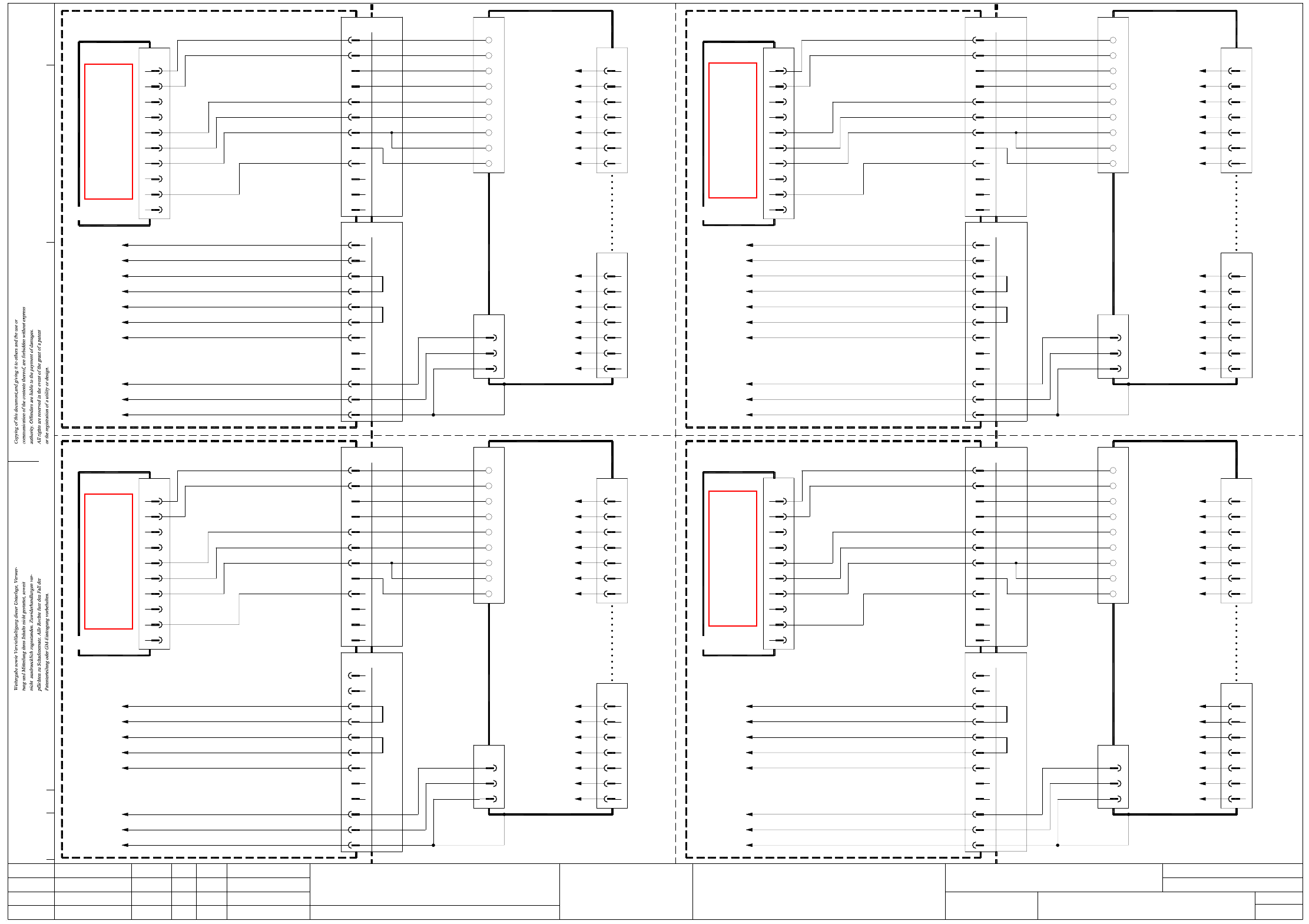
BEW-010101LD3 Interface, component trolley
n.u.
n.u.
n.u.
n.u.
n.u.
n.u.
n.u.
n.u.
n.u.
n.u.
n.u.
n.u.
n.u.
n.u.
n.u.
n.u.
n.u.
n.u.
GNYE GNYE
GNYEGNYE
CAN bus terminator, CO table
A1 03046863 (rd)
CAN bus terminator, CO table
A3 03046863 (qf)
CAN bus terminator, CO table
A3 03046863 (rf)
BK
BK
BK
BK
BK
BK
BK
WH
OG
BK
BK
BK
BK
WH
RD
BU
n.u.
n.u.
OG
RD
WH
BU
WH
BK
BK
BK
BK
BK
n.u.
n.u.
n.u.
n.u.
n.u.
n.u.
RD
WH
BU BU
WH
RD
OG
WH
BK
BK
BK BK
BK
BK
WH
OG
WH
RD
BK
BU
PK
GN
GY
YE
BN
WH
RD
BK
PK
BU
GN
YE
GY
BN
WH
RD
BK
BU
PK
GN
GY
YE
BN
BK
BK
BK
BK
BK
BK BK
BK
BK
BK
BK
BK
BK
BK
BK
BK
BK
BK
BK
B1
BK
B2
BK
B1
BK
B2
BK
B1
BK
B2
BK
B1
BK
B2
1P40V
P8V
GND_8V/40V
GND_8V/40V
P8V
1P40V
GND_8V/40V
P8V
1P40V
X25bf:3
X9bf:2
Key
10
2
C6S_End
GND
Interface
2C11
X1df
C12
3
C9
C10
C7
C8
1
PCC 43
PCC 44
L_End
S_Begin
L_Begin
C4
C5
C3
C2
C1
X1bf
B11
B12
03032352 (bf)
1
5
7
6
3
9
4
X2rf
Distributor sector 2
B1CANL
CO table 2
CANH
GND
Address_Bit 1
GND_Address
Address_Bit 0
B8
B9
B6
B7
B3
B4
B5
B2
Interface
X1bf
+30V-
GND
Spare
Input 1
Input 2
Output 2
Output 1
X13bv
4
CO trolley
Location 2
Communication unit
X15dv
2
3
1
7
6
5
2
3
X12
1
GND
+30V-
Spare
Output 1
Output 2
Input 2
Input 1
2
CO trolley
00330037
6
9
3
4
5
1
8
7
6
7
5
4
1
3
2
X1
Communication unit
X15bv
n.u.
n.u.
n.u.
n.u.
n.u.
n.u.
GND
2C11
X1cf
C12 3
C10
C9
C8
C7
1
L_End
S_Begin
L_Begin
PCC 34
PCC 33
C4
C5
C3
C2
X1af
C1
B12
B11
4
X13av
Communication unit
CO trolley
Location 1
X15cv
2
3
1
7
Spare
6
5
X12
2
+30V-
3
GND
1
00337738
WHB1CANL
CO table 1
Address_Bit 1
GND_Address
GND
Address_Bit 0
CANH
B8
B9
B7
B6
RD
BK
BU
PK
B3
B5
B4
B2
GN
GY
YE
BN
Interface
X1af
CO trolley
2
00330037
6
9
3
4
5
1
8
7
+30V-
6
7
Spare
5
4
GND
1
3
2
X1
Communication unit
X15av
2
CO trolley
B1CANL
CO table 4
03032354 (df)
00350061
C6S_End
X400:16B
X400:15A
X400:3A
X400:19A
X400:4A
D4
GND
2C11
C12 3
C10
C9
C8
C7
1
8
X400:31C
X3qf:4
X25df:3
Key
10
2
1
5
7
6
3
9
4
X2qf
B10
L_Begin
L_End
S_Begin
C4
C5
C2
C3
C1
X1df
B11
B12
CANH
Address_Bit 0
GND_Address
Address_Bit 1
GND
B8
B9
B6
B7
B3
B4
B5
B2
4
X13dv Input 2
Spare
Output 1
Output 2
Location 4
CO trolley
2
3
1
7
6
5
GND
Spare
+30V-
GND
+30V-
Input 1
Input 1
Input 2
Output 2
Output 1
2
3
X12
1
00330037
6
9
3
4
5
1
8
7
6
7
5
4
1
3
2
X1
00337738
00350061
00337738
B108
X200:16D
Distributor sector 4
X200:4A
X200:18B
X200:19B
X200:5A
D4
X9bf:1
X3rf:4
X6bf:1
ModifiedStatus Date
CAD file : BEW-010101LD3.DWG
Orig./Repl. f./Repl. byStand.Name
Check.
Stromlaufplan/Circuit diagram
Mat. no. :
Author Hi
Date
Sh.
Sh.
SIPLACE D4
1
1
CO trolley interface
Document st.
Product st.
Function st.
1. Hi
Hi1.
Hi1.
GND_Address
GND
Address_Bit 0
CANH
B8
B9
B7
B6
B3
B5
B4
B2
X12
2
+30V-
3
GND
1
00330037
6
9
3
4
5
1
8
7
+30V-
6
7
Spare
5
4
1
GND
3
2
X1
8
X100:4B
Distributor sector 3
X21af:4
X21af:2
X21af:3
X100:2D
D4
10
X21af:5
X3qd:4
X6af:1
X25af:3
X21af:6
2
Key
03032351 (af)
X2qd
CAN bus terminator, CO table
A2 03046863 (qd)
1
5
7
6
3
9
4
Distributor sector 1
B10
00337738
00350061
C6S_End
P8V
Interface
GND_8V/40V
1P40V
2
3
1
7
Spare
6
5
B10
L_End
S_Begin
L_Begin
C4
C5
C3
C2
X1cf
C1
B12
B11
Address_Bit 1
1
5
7
6
3
9
4
X13cv
4C6S_End
00350061
GND
2
C11
C12 3
C10
C9
C8
C7
1
CO trolley
Location 3
X300:4C
X300:2C
X1cf:2
X21cf:3
X300:3D
D4
8
10
X3rd:4
X6cf:1
X25cf:3
2
Key
X2rd
BEW-010101LD3
08.05.06
08.05.06
08.05.06
08.05.2006
Copyright reserved
SIEMENS AG
Output 1
Output 2
Input 2
Input 1
Input 1
Input 2
Output 2
Output 1
Output 1
Output 2
Input 2
Input 1
Input 1
Input 2
Output 2
Output 1
03032353 (cf)
2B1CANL
CO table 3 CO trolley
S
ee page 5-36
S
ee page 5-36
S
ee page 5-36
S
ee page 5-36
2 - 38
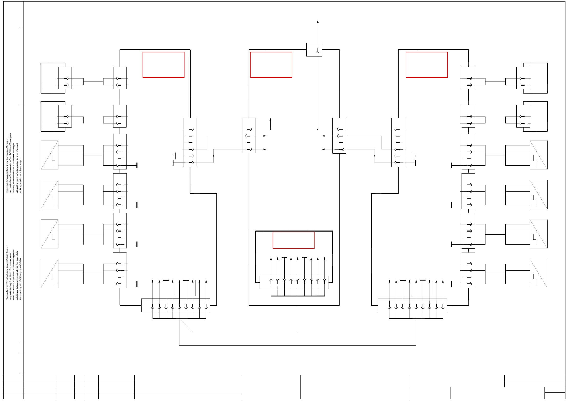
GS-010101LD3 Tape cutter, distributor, sector 4
gantry 1 and gantry 4 (sh. 1 of 2)
CANL
9-pole
S4
+5V
GND
Key
X5ah
Valve
0V
GND
+5V
+30V switchable
YE
GN
BN
Key
Key
WH
X4ah
5
GND
6
n.u.
n.u.
3
4
2
1
9
7
8
CANH
GND
n.u.
CAN_Reset
CAN_INT
3
2
BK
BN
BK
Tape cutter
Gantry 1
00329699 (ah)
X2ah
5
6
3
4
2
1
Hi1.
Hi1.
GS-010101LD3
08.05.06
08.05.06
08.05.06
08.05.2006
Copyright reserved
SIEMENS AG
X10ah
5
6
ModifiedStatus Date
CAD file : GS-010101LD3_SH01.DWG
Orig./Repl. f./Repl. byStand.Name
Check.
Stromlaufplan/Circuit diagram
Mat. no. :
Author Hi
Date
Sh.
Sh.
SIPLACE D4
1
2
Tape cutter
Document st.
Product st.
Function st.
1. Hi
5
2
RD
BK
1
2
00332894
BN
BU
BK Output
-
+
~
~
Right sensor
Piston extended
RD
BK
00332896
Signal
0V
Extend left piston
Valve
GND
Key
S3
BK6
5
3 BK
+5V
X9ah
2 BN
BK
BU
00332894
Output
-
BN +
Piston retracted
~
~
Right sensor Left sensor
Piston extended
5
GND
Key
6
BK BK Output
S2
+5V
3
2
BK
BN
X8ah
BN
BU
00332894
-
+
~
~
BK6GND
Key
S1
+5V
BK3
5
2
X7ah
BN
OutputBK
BU
BN
00332894
-
+
Piston retracted
~
~
Left sensor
BK2
0V
Valve
5 RD
X6ah
1BK
RD
00334380
2
0V
Valve
Extend right piston
Signal
~
~
Tape cutter
00329699 (dh)
Gantry 4
4
6
5
3
2
X2dh
1
+30V switchable
+5V
GND
9-poleX4dh
CANH7
CANL
CAN_INT
GND
n.u.
n.u.
GND
4
2
1
3
5
6
CAN_Reset
n.u.
8
9
00332896
00332894
X5dh
X7dh
Left sensor
Piston retracted
Valve
Extend left piston
1
2
0V
Signal
RD
BK
BN
BU
BKOutput
-
+BN
BK
BK
RD
BK 2
5
2
3
5
6
Valve
0V
Key
+5V
S1
GND
BN
GN
YE
WH
Key
Key
Extend right piston
Valve
Signal
2
1
0V
BK
RD
00334380
X6dh
BK
RD
2
5
Valve
0V
~
Piston extended
Left sensor
Output BK
+
-
~
BU
BN
BK 6
5
00332894
BK
BN
3
2
GND
Key
+5V
S2
X8dh
+5V
~
Piston retracted
~
Right sensor
-
Output BK
BU
00332894
6BK
BK
5
3
GND
Key
S3
+BN BN
X9dh
2
~
Right sensor
Piston extended
+
Output
-
~
BK
BU
BN
X10dh
00332894
BK 6
5
BK
BN
3
2
S4
GND
Key
+5V
ADR1_1
CANL
ADR1_0
GND
n.u.
GND
3
X5qe
1
2
5
4
6
GND_ADR1
n.u.
CANH
8
7
9
CAN interface
03032346
03032412
03032412
X15df
1
4-pole
WH
03032390
To sheet 2
X12bf:1
4
3
WH
X14df
2
1
BK
PK
n.u.
4
3
GND
+5V
Ctrl_TapeCutter
X11df
2
1
03032354 (df)
Distributor sector 4
(main)
WH
PK
BK
X400:5B
X400:10B
X400:6D
X400:10C
X22df:3
GN+YEGND
n.u.
GN+YE
+5V
Ctrl_TapeCutter
03032384 03032383
Gantry 1 and gantry 4
Distributor sector 4
S
ee page 5-2
S
ee page 3-9
S
ee page 5-2
S
ee page 5-20
2 - 39
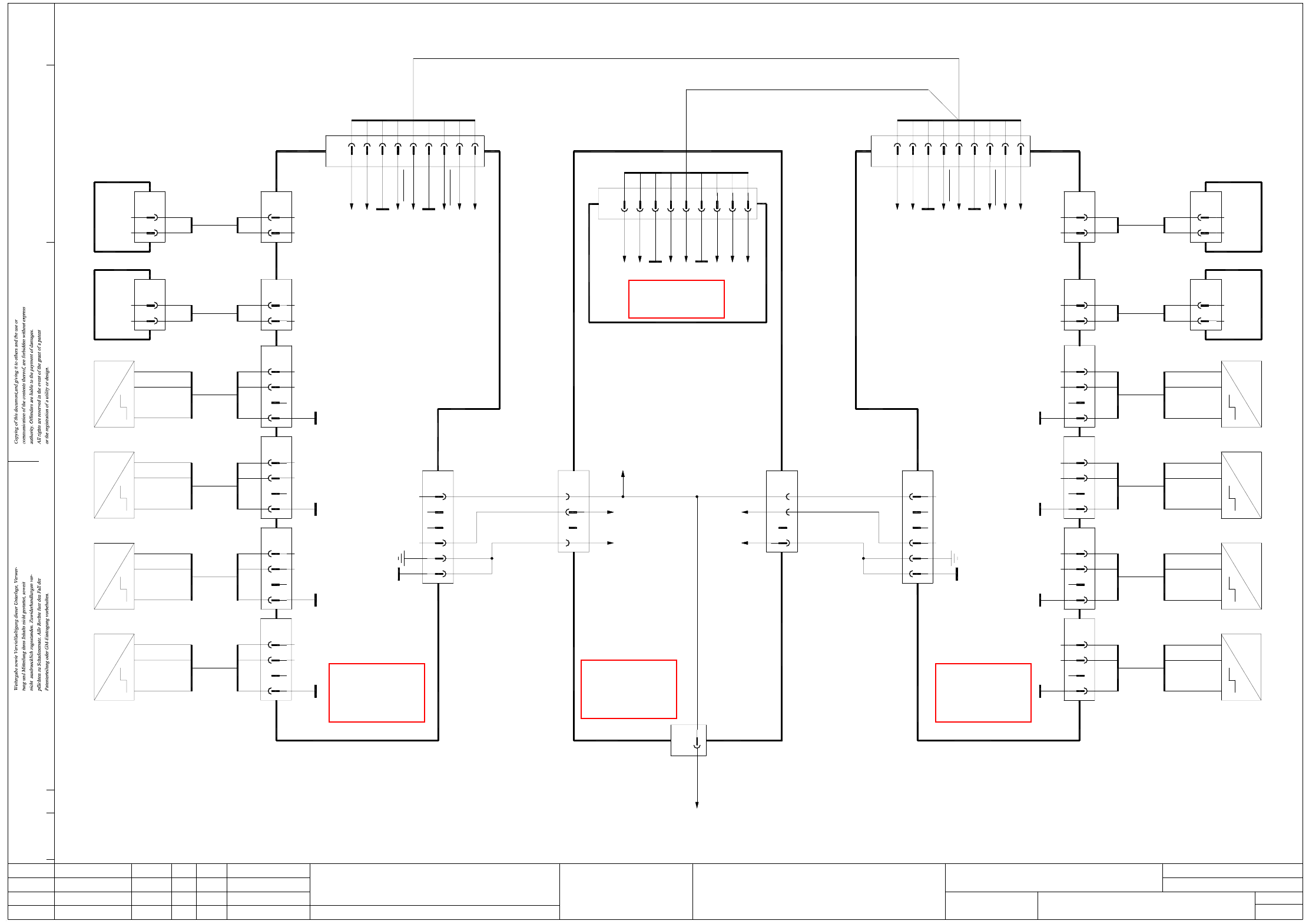
GS-010101LD3 Tape cutter, distributor, sector 2
gantry 2 and gantry 3 (sh. 2 of 2)
ModifiedStatus Date
CAD file : GS-010101LD3_SH02.DWG
Orig./Repl. f./Repl. byStand.Name
Check.
Stromlaufplan/Circuit diagram
Mat. no. :
Author Hi
Date
Sh.
Sh.
SIPLACE D4
2
2
Tape cutter
Document st.
Product st.
Function st.
1. Hi
Hi1.
Hi1.
~
Right sensor Left sensor
Piston extended
5
GND
Key
6
BK BK Output
S2
+5V
3
2
BK
BN
X8bh
BN
BU
00332894
-
+
~
~
BK6GND
Key
S1
+5V
BK3
5
2
X7bh
BN
OutputBK
BU
BN
00332894
-
+
Piston retracted
~
~
Left sensor
BK2
0V
Valve
5 RD
X6bh
1BK
RD
00334380
2
0V
Valve
Extend right piston
Signal
~
~
Tape cutter
00329699 (ch)
Gantry 3
4
6
5
3
2
X2ch
1
+30V switchable
+5V
GND
00332896
00332894
X5ch
X7ch
BN
BU
BK Output
-
+
~
~
Right sensor
Piston extended
RD
BK
00332896
Signal
0V
Extend left piston
Valve
GND
Key
S3
BK6
5
3 BK
+5V
X9bh
2 BN
BK
BU
00332894
Output
-
BN +
Piston retracted
~
BN
Key
Key
WH
S4
+5V
GND
Key
X5bh
Valve
0V
5
2
RD
BK
1
2
00332894
BK
BN
BK
Tape cutter
Gantry 2
00329699 (bh)
X2bh
5
6
3
4
2
1
GND
+5V
+30V switchable
YE
GN
GS-010101LD3
08.05.06
08.05.06
08.05.06
08.05.2006
Copyright reserved
SIEMENS AG
X10bh
5
6
3
2
Gantry 2 and gantry 3
Distributor sector 2
8CAN_Reset
n.u.
9-pole
1
X4ch
GND
n.u.
GND
CAN_INT
CANL
CANH
3
2
4
6
5
7
n.u. 9
9-pole
CANL
CAN_INT
GND
n.u.
n.u.
2
X4bh
1
3
4
5
CAN_Reset
n.u.
CANH
GND
7
6
8
9
CAN interface
ADR1_1 1
X5re
2
3GND
CANL
GND_ADR1
ADR1_0
5
4
6
n.u.
GND
8
7
9
n.u.
CANH
03032346
03032422
03032422
BK
Left sensor
Piston retracted
Valve
Extend left piston
1
2
0V
Signal
RD
BK
BN
BU
BKOutput
-
+BN
BK
BK
RD
BK 2
5
2
3
5
6
Valve
0V
Key
+5V
S1
GND
BN
GN
YE
WH
Key
Key
Extend right piston
Valve
Signal
2
1
0V
BK
RD
00334380
X6ch
BK
RD
2
5
Valve
0V
~
Piston extended
Left sensor
Output BK
+
-
~
BU
BN
BK 6
5
00332894
BK
BN
3
2
GND
Key
+5V
S2
X8ch
+5V
~
Piston retracted
~
Right sensor
-
Output BK
BU
00332894
6BK
BK
5
3
GND
Key
S3
+BN BN
X9ch
2
~
Right sensor
Piston extended
+
Output
-
~
BK
BU
BN
X10ch
00332894
BK 6
5
BK
BN
3
2
S4
GND
Key
+5V
X12bf
1
6-pole
WH
03032390
To sheet 1
X15df:1
4
3
WH
X14bf
2
1
BK
PK
n.u.
4
3
GND
+5V
Ctrl_TapeCutter
X11bf
2
1
03032352 (bf)
Distributor sector 2
(sub-)
WH
PK
BK
X200:8C
X200:10C
X200:8D
X200:10B
X2bf:1
GN+YEGND
n.u.
GN+YE
+5V
Ctrl_TapeCutter
03032406 03032405
S
ee page 5-2
S
ee page 3-3
S
ee page 5-2
S
ee page 5-20