D4+circuit(2006).pdf - 第97页
3 - 2 0303235 1-040 101LD3 Distributo r , sector 1 (sh. 2 of 2) Verteiler Sektor 1 Distributor, sector 1 03032351-040101LD3 2 23.03.2005 Huber M. US02 T eki n 08.06.05 FS0 4 P34 --> P40 HM RS02 R120 e liminate 15.06.0…
3 - 1
3 Circuit diagrams
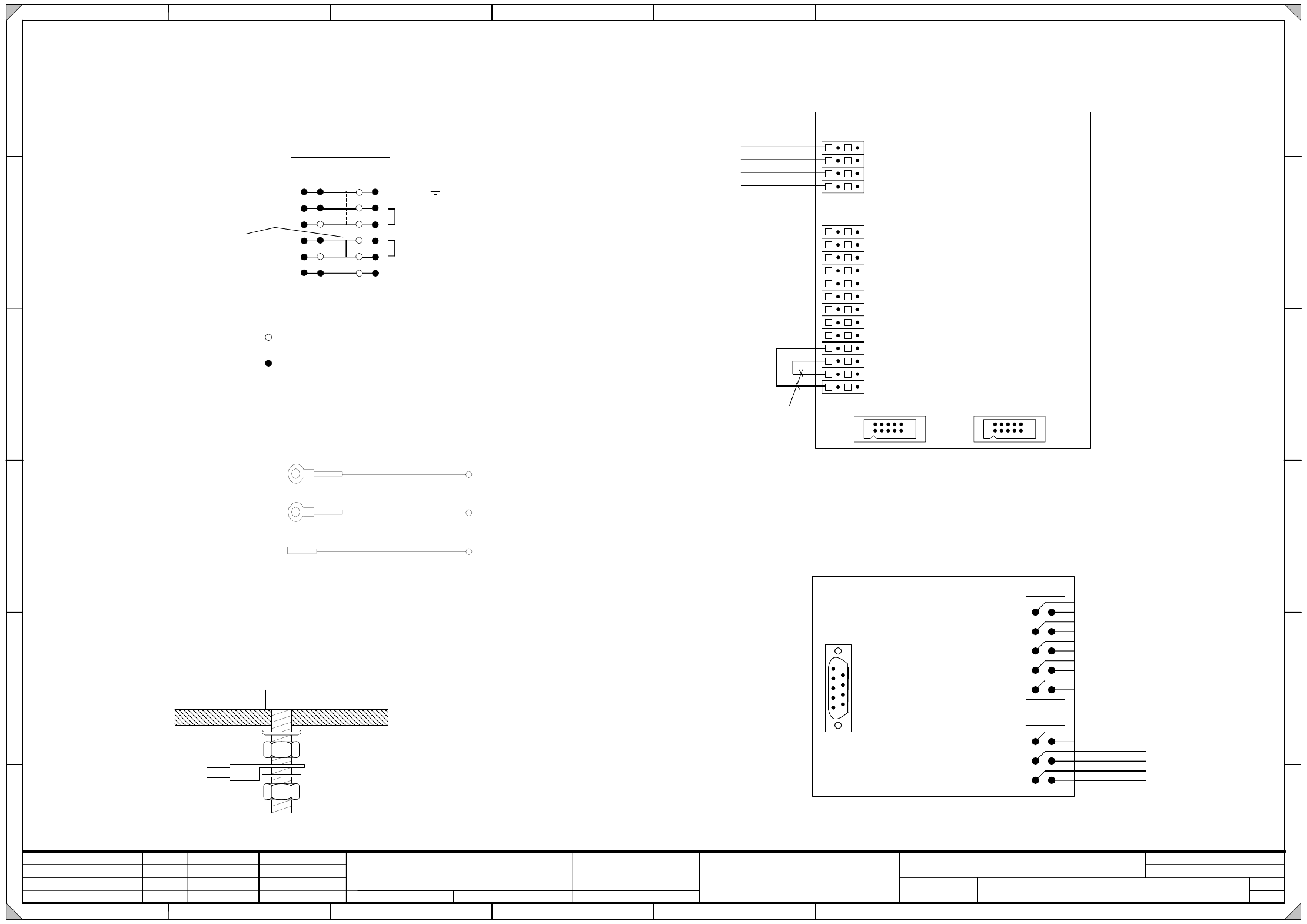
03032351-040101LD3 Distributor, sector 1 (sh. 1 of 2)
Verteiler Sektor 1
Distributor, sector 1
03032351-040101LD3
2
23.03.2005
Huber M.
US02 Tekin08.06.05
FS04
P34 --> P40
HM
RS02 R120 eliminate 15.06.05
HM16.01.06
402216
Orig. Repl. by.Repl. f.
W
e
i
t
e
r
g
a
b
e
s
o
w
i
e
V
e
r
v
i
e
l
f
ä
l
t
i
g
u
n
g
d
i
e
s
e
r
U
n
t
e
r
l
a
g
e
,
V
e
r
w
e
r
t
u
n
g
u
n
d
M
i
t
t
e
i
l
u
n
g
i
h
r
e
s
I
n
h
a
l
t
s
n
i
c
h
t
g
e
s
t
a
t
t
e
t
,
s
o
w
e
i
t
n
i
c
h
t
a
u
s
d
r
ü
c
k
l
i
c
h
z
u
g
e
s
t
a
n
d
e
n
.
Z
u
w
i
d
e
r
h
a
n
d
l
u
n
g
e
n
v
e
r
p
f
l
i
c
h
t
e
n
z
u
S
c
h
a
d
e
n
e
r
s
a
t
z
.
A
l
l
e
R
e
c
h
t
e
v
o
r
b
e
h
a
l
t
e
n
,
i
n
s
b
e
s
o
n
d
e
r
e
f
ü
r
d
e
n
F
a
l
l
d
e
r
P
a
t
e
n
t
e
r
t
e
i
l
u
n
g
o
d
e
r
G
M
-
E
i
n
t
r
a
g
u
n
g
.
P
r
o
p
r
i
e
t
a
r
y
d
a
t
a
,
c
o
m
p
a
n
y
c
o
n
f
i
d
e
n
t
i
a
l
.
A
l
l
r
i
g
h
t
s
r
e
s
e
r
v
e
d
.
C
o
n
f
i
e
a
t
i
t
r
e
d
e
s
e
c
r
e
t
d
'
e
n
t
r
e
p
r
i
s
e
.
T
o
u
s
d
r
o
i
t
s
r
e
s
e
r
v
e
s
.
C
o
m
u
n
i
c
a
d
o
c
o
m
o
s
e
g
r
e
d
o
e
m
p
r
e
s
a
r
i
a
l
.
R
e
s
e
r
v
a
d
o
s
t
o
d
o
s
o
s
d
i
r
e
i
t
o
s
.
C
o
n
f
i
a
d
o
c
o
m
o
s
e
c
r
e
t
e
i
n
d
u
s
t
r
i
a
l
.
N
o
s
r
e
s
e
r
v
a
m
o
s
t
o
d
o
s
l
o
s
d
e
r
e
c
h
o
s
.
21 786543
21 786543
A
B
C
D
E
F
A
B
C
D
E
F
Date
Author
Checked
StandardNameModificationStat. Date
Sheet
Designer 9
Copyright reserved
SIEMENS AG
Item name / Benennung
of
Document No. /
Dokumentennummer:
SIPLACE D4
1
Klemme frei / Terminal not used
Klemme gelegt / Terminal used
Jumper
Querbruecker
1
2
5
4
6
PE
Erde
Ground
GND
+24V
3
X100 terminal overview
Klemmenuebersicht X100
a
cbd
P48V
X100_1A
Erdung PE Verteiler
Distributor grounding (PE)
X1qd
CAN-Bus Abschluss
Be-Tisch
CAN bus terminator
Component table
A2 (qd)
GNYE (UL) / 2,5mm²
X1qc
X3qc
9
10
1
2
X4qc
9
10
1
2
1
2
3
5
84
1
14
2613
X2qc
Leiterplatte 1028
Vision DC/DC Wandler
Board 1028
vision DC/DC converter
A1 (qc)
10
9
11
12
X100_3A
X100_2A
X100_6A
X100_6B
GY (UL) / 1,5mm²
GY (UL) / 1,5mm²
WH (UL) / 1,5mm²
WH (UL) / 1,5mm²
BK (UL) / 1,5mm²
Kamerabeleuchtung
Portal 1 und 4
Camera lighting
Gantry 1 and 4
Kamerabeleuchtung
Portal 2 und 3
Camera lighting
Gantry 2 and 3
X100_1D
GNYE (UL) / 2,5mm²
Erdung PE X1af
X1af grounding (PE)
X100_1B
Erdung PE Maschinenständer
Maschine frame grounding (PE)
GNYE (UL) / 2,5mm²
length= 350mm
SUBD
CAN-BUS: 500kbit/s
Bestückbereich 1
Placement area 1
X3qd
X6af_2
X3af_2
Key
1
2
3
4
5
6
BK (UL) / 0,5mm²
BK (UL) / 0,5mm²
BK (UL) / 0,5mm²
BK (UL) / 0,5mm²
X100_2B
X1af_C5
10
9
X2qd
8
7
6
5
4
3
2
1
Key
Zu X1af Modul B
To X1af B module
Schraube / Bolt
Kontaktscheibe / Contact washer
Mutter DIN439 / DIN439 nut
Kabelschuhring / Annular cable lug
Mutter DIN439 / DIN439 nut
Sperrkantscheibe / Serrated lock washer
Blech / Plate
Erdungsanschluss nach Bauvorschrift 90010850-XXXXXXBD4:
Grounding terminal according to d esign specification 90010850-XXXXXXBD4:
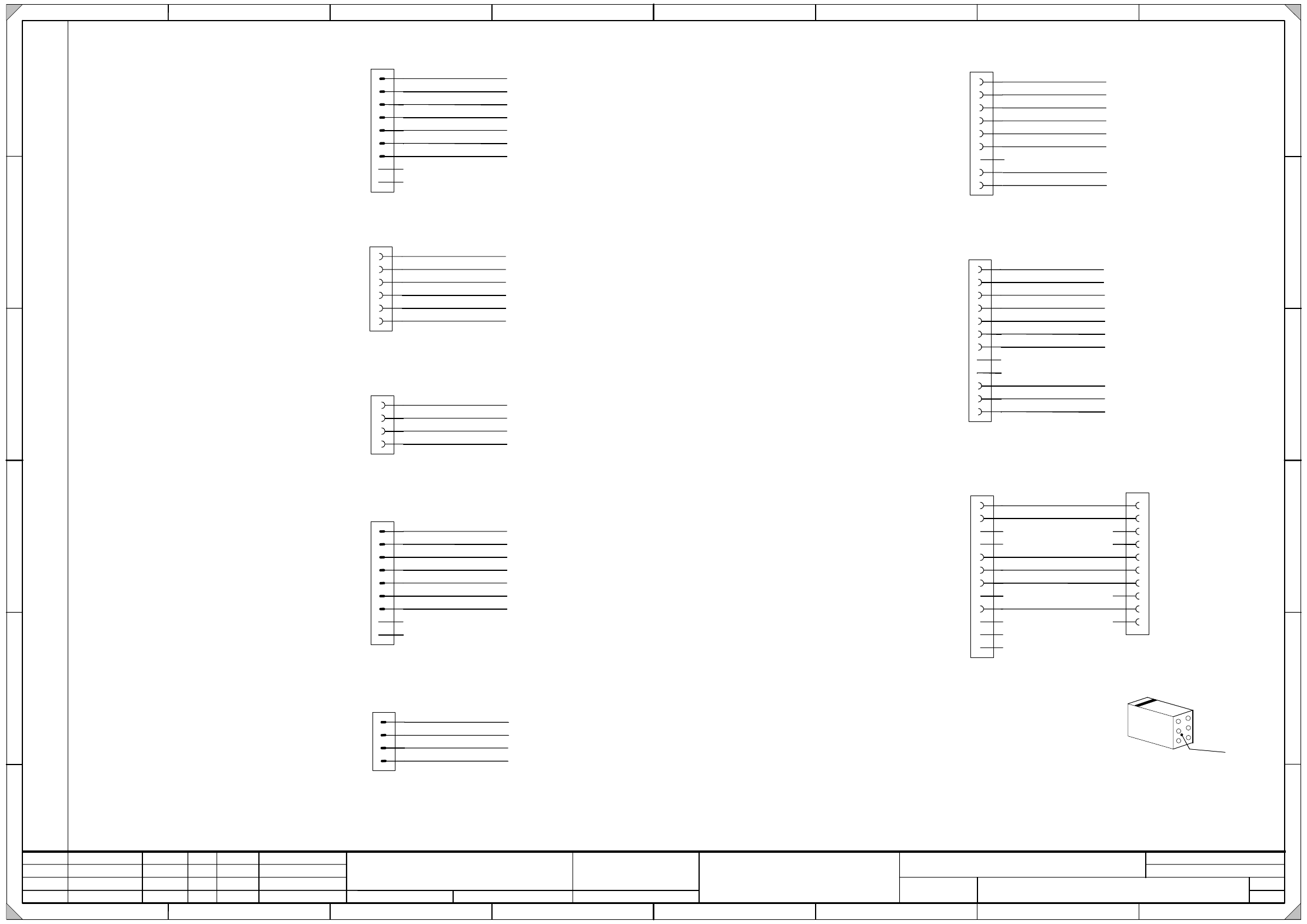
3 - 2
03032351-040101LD3 Distributor, sector 1 (sh. 2 of 2)
Verteiler Sektor 1
Distributor, sector 1
03032351-040101LD3
2
23.03.2005
Huber M.
US02 Tekin08.06.05
FS04
P34 --> P40
HM
RS02 R120 eliminate 15.06.05
HM16.01.06
402216
Orig. Repl. by.Repl. f.
W
e
i
t
e
r
g
a
b
e
s
o
w
i
e
V
e
r
v
i
e
l
f
ä
l
t
i
g
u
n
g
d
i
e
s
e
r
U
n
t
e
r
l
a
g
e
,
V
e
r
w
e
r
t
u
n
g
u
n
d
M
i
t
t
e
i
l
u
n
g
i
h
r
e
s
I
n
h
a
l
t
s
n
i
c
h
t
g
e
s
t
a
t
t
e
t
,
s
o
w
e
i
t
n
i
c
h
t
a
u
s
d
r
ü
c
k
l
i
c
h
z
u
g
e
s
t
a
n
d
e
n
.
Z
u
w
i
d
e
r
h
a
n
d
l
u
n
g
e
n
v
e
r
p
f
l
i
c
h
t
e
n
z
u
S
c
h
a
d
e
n
e
r
s
a
t
z
.
A
l
l
e
R
e
c
h
t
e
v
o
r
b
e
h
a
l
t
e
n
,
i
n
s
b
e
s
o
n
d
e
r
e
f
ü
r
d
e
n
F
a
l
l
d
e
r
P
a
t
e
n
t
e
r
t
e
i
l
u
n
g
o
d
e
r
G
M
-
E
i
n
t
r
a
g
u
n
g
.
P
r
o
p
r
i
e
t
a
r
y
d
a
t
a
,
c
o
m
p
a
n
y
c
o
n
f
i
d
e
n
t
i
a
l
.
A
l
l
r
i
g
h
t
s
r
e
s
e
r
v
e
d
.
C
o
n
f
i
e
a
t
i
t
r
e
d
e
s
e
c
r
e
t
d
'
e
n
t
r
e
p
r
i
s
e
.
T
o
u
s
d
r
o
i
t
s
r
e
s
e
r
v
e
s
.
C
o
m
u
n
i
c
a
d
o
c
o
m
o
s
e
g
r
e
d
o
e
m
p
r
e
s
a
r
i
a
l
.
R
e
s
e
r
v
a
d
o
s
t
o
d
o
s
o
s
d
i
r
e
i
t
o
s
.
C
o
n
f
i
a
d
o
c
o
m
o
s
e
c
r
e
t
e
i
n
d
u
s
t
r
i
a
l
.
N
o
s
r
e
s
e
r
v
a
m
o
s
t
o
d
o
s
l
o
s
d
e
r
e
c
h
o
s
.
21 786543
21 786543
A
B
C
D
E
F
A
B
C
D
E
F
Date
Author
Checked
StandardNameModificationStat. Date
Sheet
Designer 9
Copyright reserved
SIEMENS AG
Item name / Benennung
of
Document No. /
Dokumentennummer:
SIPLACE D4
2
+24V
+24V
X4af
1
2
3
4
X100_5A
5
6
L_Begin S_Anfang
S_Emerg.StopButton M_NotHaltTaste
S_StartButton M_StartTaste
S_StopButton M_StopTaste
L_End S_Ende
+24V
L_End S_Ende
L_Begin S_Anfang
S_hood M_Haube
L_Begin S_Anfang
L_End S_Ende
S_CompFlap M_BeKlappe
Start/StopInputRight
Emerg.StopPCBInput
Start/StopTasteErechts
NotHaltLPEingabe
Component flap 1
BeKlappe 1
Hood 1
Haube 1
X6af
5
4
6
3
2
1
7
8
9
S_hood M_Haube
S_StartButton M_StartTaste
S_Emerg.StopButton M_NotHaltTaste
S_CompFlap M_BeKlappe
S_CompEnd M_BeEnde
S_StopButton M_StopTaste
L_End S_Ende
Safety ring circuit
Sec1<>Sec2
Ringl.Sicherheit
Sek1<>Sek2
X4af_6
Spare Reserve
X3af_1
X3af_4, X6af_4
X3af_3, X6af_3
X4af_4
X25af_4
X5af_2
X4af_3
X3af_5, X6af_5
X4af_5
X5af_4
X1af_C4
X25af_2
X5af
4
3
2
1
X3af
5
4
6
3
2
1
7
8
9
S_hood M_Haube
S_StartButton M_StartTaste
S_Emerg.StopButton M_NotHaltTaste
X4af_5
X4af_6
S_CompFlap M_BeKlappe
S_CompEnd M_BeEnde
S_StopButton M_StopTaste
L_End S_Ende
Safety ring circuit
Sec4<>Sec1
Ringl.Sicherheit
Sek4<>Sek1
Spare Reserve
Spare Reserve
X4af_2
X3qd_1
X5af_4
X4af_4
X25af_4
X21af
5
4
6
3
2
1
7
8
9
+24V
1P40V
N8V/40V
X100_5D
X1af_C2
P8V
PCC33 SSK33
PCC34 SSK34
X1af_C1
P48V
N48V
X100_3D
X100_6D
X1af
C5
C4
C6
C3
C2
C1
C7
C8
C9
C10
C11
C12
Modul C
C module
X1af
B5
B4
B6
B3
B2
B1
B7
B8
B9
B10
B11
B12
Modul B
B module
Component table socket
BeTisch-Stecker
Spare Reserve
L_Begin S_Anfang
1P40V
P8V
SSK33
SSK34
GND_8V/40V
L_End S_Ende
GND
S_Begin M_Anfang
S_End M_Ende
GND
CANL
CANH
Spare Reserve
Spare Reserve
Spare Reserve
Spare Reserve
Spare Reserve
Adress_Bit 0
Adress_Bit 1
GND_Adress
Spare Reserve
Spare Reserve
X3qd_4
X25af_3
X6af_1
X100_2D
X21af_5
X21af_6
X21af_2
X21af_3
X21af_4
X1af_C10
X1af_C11
X1af_C12
X100_4B
BK (UL) / 1,0mm²
BK (UL) / 0,5mm²
BK (UL) / 1,0mm²
BK (UL) / 1,0mm²
BK (UL) / 1,0mm²
BK (UL) / 1,0mm²
BK (UL) / 1,0mm²
BK (UL) / 1,0mm²
BK (UL) / 1,0mm²
BK (UL) / 1,0mm²
BK (UL) / 1,0mm²
BK (UL) / 1,0mm²
OG (UL) / 2,5mm²
BK (UL) / 1,0mm²
BK (UL) / 1,0mm²
BK (UL) / 1,0mm²
OG (UL) / 2,5mm²
BK (UL) / 1,0mm²
BK (UL) / 1,0mm²
BK (UL) / 1,0mm²
BK (UL) / 1,0mm²
BK (UL) / 1,0mm²
BK (UL) / 0,5mm²
BK (UL) / 1,0mm²
WH (UL) / 1,0mm²
BK (UL) / 1,0mm²
BK (UL) / 1,0mm²
BU
(UL) / 1,0mm²
RD (UL) / 1,0mm²
OG (UL) / 2,5mm²
GY (UL) / 2,5mm²
WH (UL) / 2,5mm²
BK (UL) / 1,0mm²
BK (UL) / 1,0mm²
BK (UL) / 1,0mm²
BK (UL) / 1,0mm²
BK (UL) / 0,5mm²
OG (UL) / 2,5mm²
WH (UL) / 1,0mm²
BU (UL) / 1,0mm²
RD (UL) / 1,0mm²
WH (UL) / 1,0mm²
BK (UL) / 0,5mm²
BK (UL) / 0,5mm²
BK (UL) / 0,5mm²
BK (UL) / 0,5mm²
BK (UL) / 0,5mm²
BK (UL) / 0,5mm²
X100_4A
X3af_7, X6af_7
X25af
1
2
3
4
BK (UL) / 1,0mm²
BK (UL) / 1,0mm²
X3af_6, X6af_6
X5af_3
X1af_C3
X100_4D
BK (UL) / 1,0mm²
OG (UL) / 2,5mm²
Spare Reserve
Spare Reserve
Infeed
distributor, sector 4
voltages, PCC, vision
Speisung
Verteiler Sektor 4
Spannungen, SSK, Vision
X3qd_2
X2qd
2
3
4
5
1
7
10
Key
A2 (qd)
CAN-Bus Abschluss
BE-Tisch
CAN bus terminator
Component table
Zu beachten ist, dass ...
die Zählfolge eines Locking-Clip-Steckers von der
Rückseite des Gehäuses betrachtet werden muss.
1
3
5
2
4
6
Kabel
Cable
Please note that ...
the numerical sequence of a locking clip plug
must be as viewed from the rear side of the casing.
Locking-Clip_Stecker X2qd und X3qd:
Locking clip plug X2qd and X3qd:
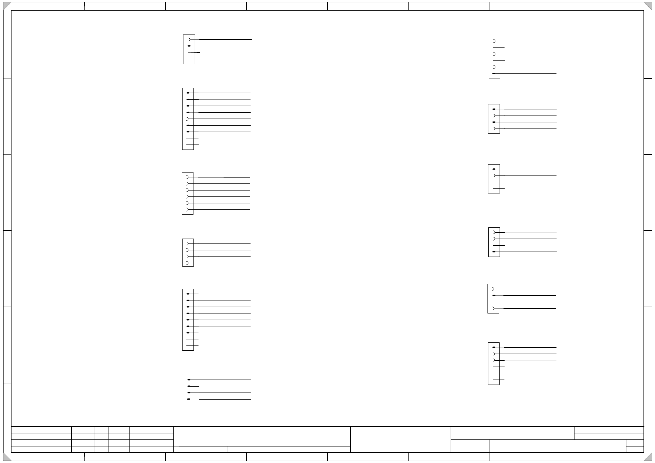
3 - 3
03032352-040101LD3 Distributor, sector 2 (sh. 1 of 4)
Verteiler Sektor 2
Distributor sector 2
03032352-040101LD3
4
23.03.2005
Huber M.RS02
HM
07.06.05S1: switch status
FS03
modification X21bf 19.05.05
HM
HM
402216
FS04
16.01.06
Orig. Repl. by.Repl. f.
W
e
i
t
e
r
g
a
b
e
s
o
w
i
e
V
e
r
v
i
e
l
f
ä
l
t
i
g
u
n
g
d
i
e
s
e
r
U
n
t
e
r
l
a
g
e
,
V
e
r
w
e
r
t
u
n
g
u
n
d
M
i
t
t
e
i
l
u
n
g
i
h
r
e
s
I
n
h
a
l
t
s
n
i
c
h
t
g
e
s
t
a
t
t
e
t
,
s
o
w
e
i
t
n
i
c
h
t
a
u
s
d
r
ü
c
k
l
i
c
h
z
u
g
e
s
t
a
n
d
e
n
.
Z
u
w
i
d
e
r
h
a
n
d
l
u
n
g
e
n
v
e
r
p
f
l
i
c
h
t
e
n
z
u
S
c
h
a
d
e
n
e
r
s
a
t
z
.
A
l
l
e
R
e
c
h
t
e
v
o
r
b
e
h
a
l
t
e
n
,
i
n
s
b
e
s
o
n
d
e
r
e
f
ü
r
d
e
n
F
a
l
l
d
e
r
P
a
t
e
n
t
e
r
t
e
i
l
u
n
g
o
d
e
r
G
M
-
E
i
n
t
r
a
g
u
n
g
.
P
r
o
p
r
i
e
t
a
r
y
d
a
t
a
,
c
o
m
p
a
n
y
c
o
n
f
i
d
e
n
t
i
a
l
.
A
l
l
r
i
g
h
t
s
r
e
s
e
r
v
e
d
.
C
o
n
f
i
e
a
t
i
t
r
e
d
e
s
e
c
r
e
t
d
'
e
n
t
r
e
p
r
i
s
e
.
T
o
u
s
d
r
o
i
t
s
r
e
s
e
r
v
e
s
.
C
o
m
u
n
i
c
a
d
o
c
o
m
o
s
e
g
r
e
d
o
e
m
p
r
e
s
a
r
i
a
l
.
R
e
s
e
r
v
a
d
o
s
t
o
d
o
s
o
s
d
i
r
e
i
t
o
s
.
C
o
n
f
i
a
d
o
c
o
m
o
s
e
c
r
e
t
e
i
n
d
u
s
t
r
i
a
l
.
N
o
s
r
e
s
e
r
v
a
m
o
s
t
o
d
o
s
l
o
s
d
e
r
e
c
h
o
s
.
21 786543
21 786543
A
B
C
D
E
F
A
B
C
D
E
F
Date
Author
Checked
StandardNameModificationStat. Date
Sheet
Designer 9
Copyright reserved
SIEMENS AG
Item name / Benennung
of
Document no. /
Dokumentennummer:
SIPLACE D4
1
+24V
X4bf_1, X25bf_1
X5bf_1
X4bf
1
2
3
4
5
6
L_Begin S_Anfang
S_Hood M_Haube
S_StartButton M_StartTaste
S_StopButton M_StopTaste
L_End S_Ende
+24V
L_End S_Ende
L_Begin S_Anfang
S_Hood M_Haube
Start/StopButtonOutputRight
HoodPCBOutput
Start/StopTasteARechts
HaubeLPAusgabe
Component flap 2
BeKlappe 2
Hood 2
Haube 2
X6bf_7,
X3bf_7,
X6bf
5
4
6
3
2
1
7
8
9
S_Hood M_Haube
S_StartButton M_StartTaste
S_Emerg.StopButton M_NotHaltTaste
S_CompFlap M_BeKlappe
S_CompEnd M_BeEnde
S_StopButton M_StopTaste
L_End S_Ende
Safety ring circuit
Sec2<>Sec3
Ringl.Sicherheit
Sek2<>Sek3
X10bf_3, X4bf_6
Spare Reserve
Spare Reserve
X3bf_1
X3bf_3, X5bf_4
X4bf_4, X6bf_3
X3bf_4
X3bf_6, X6bf_6
X25bf_4
X5bf_2
X4bf_3
X3bf_5, X6bf_5
X10bf_2, X4bf_5
X5bf_4
X25bf_2
X5bf_3
X1bf_C3
X5bf
4
3
2
1
X8bf
1
2
3
4
X200_12A
Verteiler 2 +24V
Verteiler 3 +24V
Verteiler 2 GND
Verteiler 3 GND
Infeed
cable carrier distributor 2, 3
Speisung
Schlepp Verteiler 2, 3
X9bf
1
2
3
4
X11bf
1
2
3
4
Ctrl_EmptyTapeCut. St_Gurts.
+5V
GND
Infeed
empty tape cutter 2
Speisung
Gurtschneider 2
Spare Reserve
X14bf
1
2
3
4
Ctrl_EmptyTapeCut. St_Gurts.
+5V
GND
Infeed
empty tape cutter 3
Speisung
Gurtschneider 3
Spare Reserve
X2bf
1
2
3
4
X14bf_1
Ctrl_EmptyTapeCut. St_Gurts.
X3bf
5
4
6
3
2
1
7
8
9
S_Hood M_Haube
S_StartButton M_StartTaste
S_Emerg.StopButton M_NotHaltTaste
X4bf_5
X4bf_6
S_CompFlap M_BeKlappe
S_CompEnd M_BeEnde
S_StopButton M_StopTaste
L_End S_Ende
Safety ring circuit
Sec1<>Sec2
Ringl.Sicherheit
Sek1<>Sek2
Spare Reserve
X4bf_2
X3rf_1
X4bf_4
X6bf_4
X25bf_4
X200_11A
X200_9B
X200_5C
X200_10B
X200_8D
X200_10C
Empty tape cutter
main valve
Gurtschneider
Hauptventil
GND
X200_6D
X7bf
2
3
4
5
1
X1bf_C1
X12bf
5
4
6
3
2
1
X14bf_1, X11bf_1
X10bf_2
Ctrl_EmptyTapeCut. St_Gurts.
S_StartButton M_StartTaste
S_StopButton M_StopTaste
from distributor 4
Sec 2 <> Sec 4
von Sektor 4
Sek 2 <> Sek 4
X10bf_3
Unregulated
DC voltages
Ungeregelte
DC-Spannungen
N40V
1P40V
N8V
P8V
X200_18C
PCC43 SSK43
PCC44 SSK44
X200_19C
X1bf_C4
X3rf_2
X1bf_C2
X200_8C
6
Spare Reserve
Spare Reserve
Spare Reserve
Spare Reserve
PCC
periphery
SSK
Peripherie
X200_4D
X200_5D
RD (UL) / 2,5mm²
BU (UL) / 2,5mm²
WH (UL) / 2,5mm²
WH (UL) / 2,5mm²
BK (UL) / 1,0mm²
BK (UL) / 1,0mm²
PK (UL) / 2,5mm²
WH (UL) / 2,5mm²
BK (UL) / 1,0mm²
BK (UL) / 1,0mm²
OG (UL) / 2,5mm²
WH (UL) / 2,5mm²
WH (UL) / 2,5mm²
OG (UL) / 2,5mm²
PK (UL) / 2,5mm²
WH (UL) / 2,5mm²
BK (UL) / 1,0mm²
BK (UL) / 1,0mm²
BK (UL) / 1,0mm²
BK (UL) / 1,0mm²
WH (UL) / 1,0mm²
BK (UL) / 1,0mm²
BK (UL) / 0,5mm²
BK (UL) / 1,0mm²
BK (UL) / 1,0mm²
BK (UL) / 1,0mm²
BK (UL) / 1,0mm²
BK (UL) / 1,0mm²
OG (UL) / 1,0mm²
BK (UL) / 1,0mm²
BK (UL) / 1,0mm²
BK (UL) / 1,0mm²
BK (UL) / 1,0mm²
BK (UL) / 1,0mm²
OG (UL) / 1,0mm²
BK (UL) / 1,0mm²
BK (UL) / 1,0mm²
BK (UL) / 1,0mm²
BK (UL) / 1,0mm²
BK (UL) / 0,5mm²
BK (UL) / 1,0mm²
BK (UL) / 1,0mm²
BK (UL) / 1,0mm²
BK (UL) / 1,0mm²
BK (UL) / 1,0mm²
X200_17B, X5bf_1
X12bf_1
X2bf_1, X12bf_1
Spare Reserve
Spare Reserve
Spare Reserve+24V
L_Begin S_Anfang
L_End S_Ende
S_CompFlap M_BeKlappe
X25bf
1
2
3
4
BK (UL) / 1,0mm²
BK (UL) / 1,0mm²
BK (UL) / 1,0mm²
OG (UL) / 1,0mm²
Spare Reserve