_414214_AVK3 服务手册.pdf - 第121页
6.9 T iming Belt T ension Measurement (Sonic T ension Meter) SERVICE MANUAL A VK3 6.9−4 D77SEC−85−210−A0
6.9 Timing Belt Tension Measurement (Sonic Tension Meter)
SERVICE MANUAL
AVK3
6.9−3
D77SEC−85−210−A0
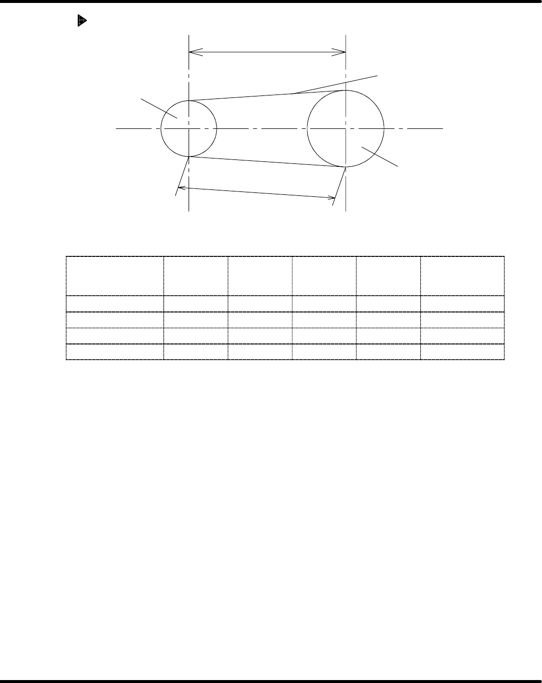
Belt tensioning Value
distance between axes
span
pulley
pulley
timing belt
=NOTE=
Make sure that distance between axes and span are not same.
axis
H axis(Up-
per Drive)
WH axis
(Insertion
Unit)
WA axis
(Upper
Anvil)
T axis
(Transfer
Chuck))
H axis(Upper
Drive Encord-
er))
Weight(g/cm
2
) 5.2 2.5 2.5 4 2.5
Belt width(mm) 40 6 6 15 9
span(mm) 190 123 62 101 99.5
tension,N(kgf) 500.5(51) 29.5(3) 29.5(3) 137.5(14) 44.1(4.5)

6.9 Timing Belt Tension Measurement (Sonic Tension Meter)
SERVICE MANUAL
AVK3
6.9−4
D77SEC−85−210−A0
6.10 Mechanical Lock Composition and Handling
SERVICE MANUAL
AVK3
6.10−1
D77SEC−85−220−A0
6.10 Mechanical Lock Composition and Handling
D77SEC−85−220−A0
Sentence No.
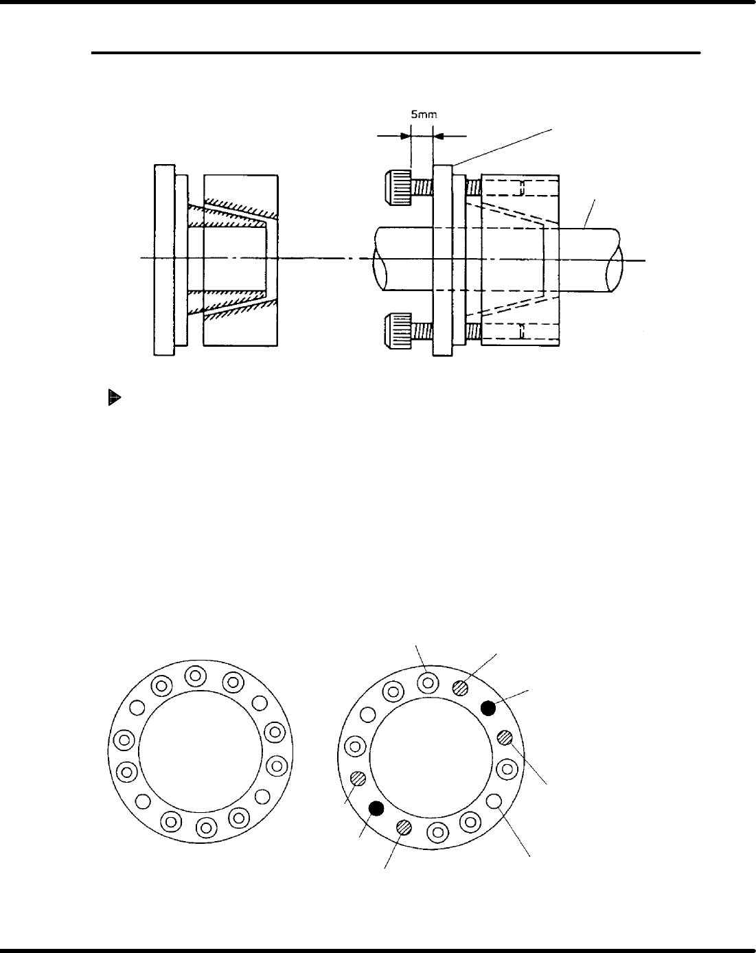
Composition
Flange
Shaft
Release the lock
1. Loosen all the mechanical lock bolts.
• Loosen so that the bolts are about 5mm from the surface of the flange.
2. Remove the 4 bolts from the mechanical lock tap holes on both sides.
• This is because the 4 bolts to release the lock will interfere with each other and will not turn.
=NOTE=
Do not remove all of the mechanical lock bolts. Always leave 1 bolt in place.
(The holes will not line up again)
3. Attach 2 removed bolts in the opposing tap holes.
4. Uniformly tighten those 2 bolts and they will becomes unlocked when you hear a clicking
sound.
Bolt
Remove bolt
Lock release bolt
Remove bolt
Tap hole
Remove bolt
Lock release bolt
Remove
bolt