_414214_AVK3 服务手册.pdf - 第28页
2.1 Installation Procedure SERVICE MANUAL A VK3 2.1−3 D77SEC−1 1−040−A0 2.1.3 Accessories, Power Supply , Air Connections Attachments Accessories 1. Attach accessories (such as dust collector and signal tower) to the spe…
2.1 Installation Procedure
SERVICE MANUAL
AVK3
2.1−2
D77SEC−11−040−A0
2.1.2 Leveling Machine
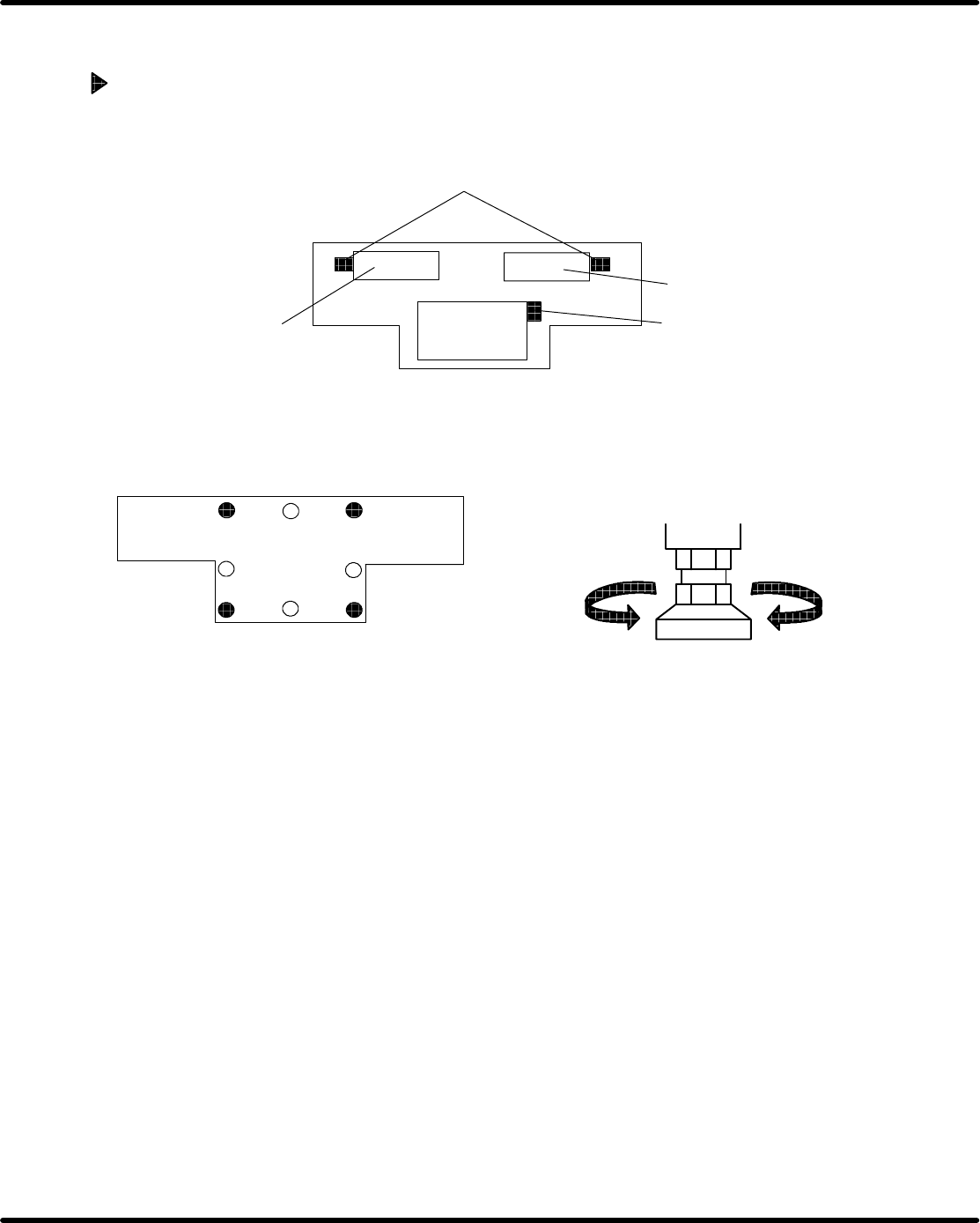
Leveling machine
1. Set machine main body accurately on the reference points.
2. Remove fixtures (for transportation) from X, Y, Z axes, etc.
Left feeder carriage
XY table
Z axis fixtures (2 pcs.)
XY axis fixture (1 pc.)
Right feeder carriage
=NOTE=
Make sure that feeder carriage sensor dogs do not interfere with the feeder carriage
sensors.
3. The machine main body is secured by 4 legs. Other legs are allowed to float.
DOWN
1 Rotation:3.5mm
Adjust bolt
4. Adjust the 4 legs and decide height from floor to transfer belt surface.
=Specification=
Height : 915±5mm
5. Set the level on the abraded face of XY table, adjust 4 legs to level the machine, and tighten
with locknuts. Place the levels in the designated positions on the machine (use 2 levels).
=NOTE=
Check that the levels are calibrated.
6. Adjust all other legs, and make sure the machine is still leveled (for AVK3, 8 − 4 = 4 legs).
7. Tighten all legs with locknuts and make sure the machine is still leveled. (check that there
are no floating legs).
2.1 Installation Procedure
SERVICE MANUAL
AVK3
2.1−3
D77SEC−11−040−A0
2.1.3 Accessories, Power Supply, Air Connections
Attachments
Accessories
1. Attach accessories (such as dust collector and signal tower) to the specified positions.
Air connections
1. Attach the primary side air tubing to the machine body and check the pneumatic pressure.
=Specification=
Air pressure: 0.5 MPa
=NOTE=
Remove oil or dirt from inside of the air tubing before connecting it.
Connection of primary side power supply
1. Check the voltage of primary side 3−phase power supply with the tester. (Electric power dis-
tribution on the factory side)
2. Check that the voltage of the tap connected to the built−in transformer is the same as the
factory power voltage.
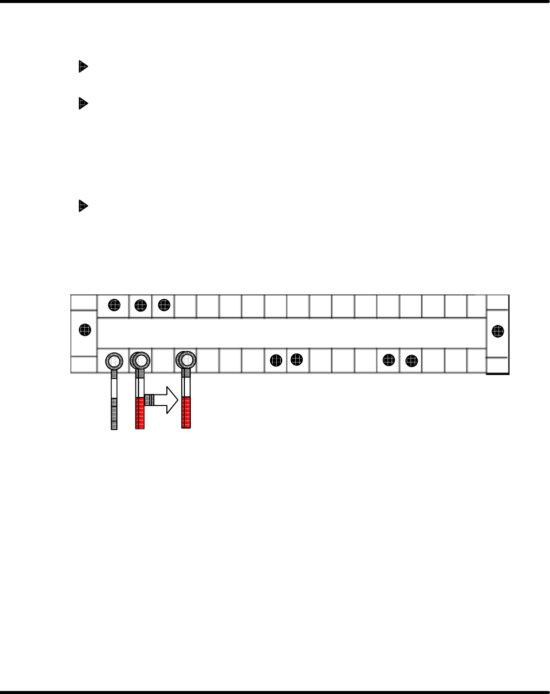
3. If not, change the connection of built−in transformer. ........U, V, W
[EX.] Primary power supply of the factory: 380 V (Right terminal stand)
Move the wire connected to 200 V to the terminal of 380 V.
U
U
220V
200V
380V
400V
420V 480V
V
200V
UU
U
U
W
200V
W
・・・・
・・・・
V
U
4. Connect primary 3−phase power supply on the factory side to main switch of the machine
and recheck the voltage with the tester
5. Turn ON the main switch and check the secondary side voltage of the built−in transformer
with the tester.
=Specification=
Voltage: AC200V±10V or below (3−phase)
Voltage: AC100V±5V or below
6. When the dust collector and other equipment are driven by 3−phase 200V power supply,
check the rotational direction of the dust collector with the main breaker [ON], machine pow-
er [ON] and ”SERVO MOTOR” on the main control panel [OFF].
If the rotational direction is not correct, change the phase of 3−phase power supply (Change
R−phase for V−phase.).

2.1 Installation Procedure
SERVICE MANUAL
AVK3
2.1−4
D77SEC−11−040−A0
=NOTE=
Make sure that the main breaker at the primary side is turned [OFF] when changing
the phase of 3−phase power supply.