_414214_AVK3 服务手册.pdf - 第34页
2.1 Installation Procedure SERVICE MANUAL A VK3 2.1−9 D77SEC−1 1−040−A0 2.1.7 Precision and Performance Check in Semi Auto Operation =NOTE= Make sure that “SEMI” on the main control panel is always [ON] when excuting the…
2.1 Installation Procedure
SERVICE MANUAL
AVK3
2.1−8
D77SEC−11−040−A0
2.1.6 Precision and Performance Check in Manual Operation
NC control card origin offset check
1. Turn the power [OFF].
2. Check that the connection of connectors inside P783 (must not be disconnected or be
loose).
3. Turn the power [ON] and return to origin.
4. Check that the DC power voltage of P783F with volt meter.
Manual operation check
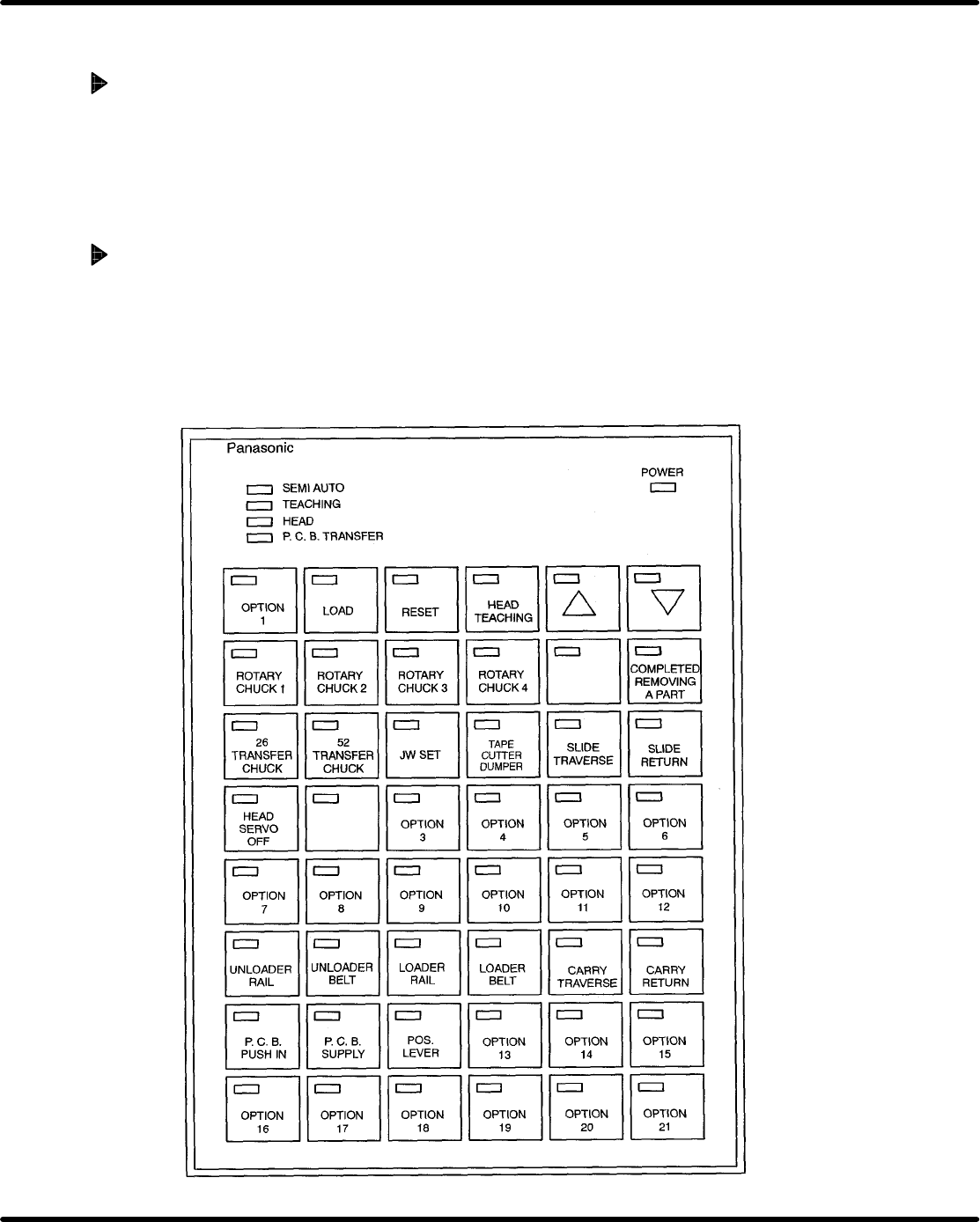
1. Check all manual switches on the sub control panel.
=NOTE=
If each cylinder speed is not proper, adjust it by the speed controller.
2. After turning all manual switches [OFF], with using the manual NC function, that each of
axes including X, Y, Z, V, W is to move by one block and in a continuous manner.
COMMON
COMMON
COMMON COMMON
COMMON
COMMON
AVK3 AVK3 AVK3 AVK3
AVK3 AVK3
COMMON COMMON
COMMON COMMON COMMON
COMMON
COMMON COMMON
COMMON
COMMON
COMMON
COMMON
COMMON
COMMON
COMMON
COMMON
COMMON
COMMON
COMMON COMMON
COMMON
COMMON
COMMON
COMMON
COMMON
COMMON COMMON COMMON
COMMON
JVK3B
26/52
PITCH
HEAD
ROTATION
PANASERT−Avk3/JVK3B Sub Control Panel
AVK3 AVK3 AVK3 AVK3
AVK3 AVK3
2.1 Installation Procedure
SERVICE MANUAL
AVK3
2.1−9
D77SEC−11−040−A0
2.1.7 Precision and Performance Check in Semi Auto
Operation
=NOTE=
Make sure that “SEMI” on the main control panel is always [ON] when excuting the
following checks.
Precision and performance check in semi auto operation
1. Select t he NC program and The parst data..
=NOTE=
The machine should contain the 416 NC program and the array program.
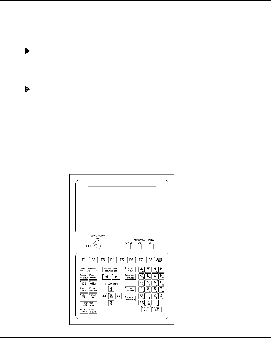
2. Turn “SEMI” on the main control panel [ON] to check the operation.
XY table and feeder carriage positioning operation
1. Check that the positioning operation as programmed can be performed every block with
turning “1 BLK” on the main control panel [ON].
2. Check that the positioning operation as programmed can be performed every block with
turning “EOP” on the main control panel [ON].
3. Check that the positioning operation as programmed can be performed every block with
turning “CONT” on the main control panel [ON].
PCB transfer operation check
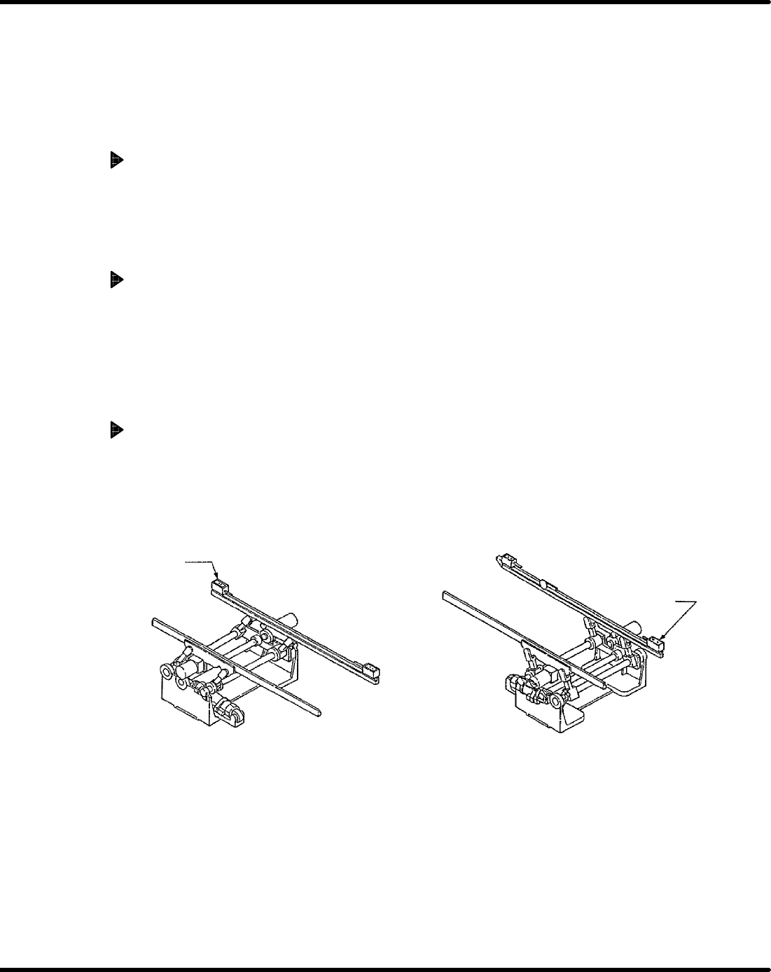
1. Turn “SEMI” on the main control panel [ON], set PCB to the right end (under LS1) of the
loader rail, and when turning “RESET” and “LOAD” on the sub control panel [ON], check
that PCB is carried into the positioner.
2. Further, in the same procedure, when another PCB is carried in, check that PCB on the po-
sitioner is carried in up to the unloader rail left end (under LS4).
LS4
Unloader
LS1
Loader
2.1 Installation Procedure
SERVICE MANUAL
AVK3
2.1−10
D77SEC−11−040−A0
2.1.8 Precision and Performance Check in Semi Auto
Operation (Include Some Manual Precision
Check)
PCB transfer operation check
1. When PCB is transferred with turning “AUTO” on the main control panel [ON], check that
no abnormality is found about its operation.
2. When turning “L. STOP” on the main control panel [ON], check that no abnormality is found
about its operation.
Recovery completion check
1. Using nippers, cut the lead on one side of the first component in the feeder.
2. Allow the machine to perform the insertion operation when turning “AUTO” on the main
control panel [ON] (Insertion error occurs).
3. Turn [ON] ”REPLACEMENT” on the main control panel and check that the feeder carriage
moves toward the outside.
4. Turn [ON] ”REPLACEMENT” on the main control panel to return the feeder carriage and
press ”START” on the main control panel to check for proper recovery.
5. Check that the component set in the feeder is properly fed (check for any shift or deforma-
tion). Then, press ”START” on the main control panel and check that the safety stop is
cleared. (”SAFETY STOP” displayed on the screen disappears.)
6. Check that “RECOVERY OK” is displayed on the control monitor.