_414214_AVK3 服务手册.pdf - 第89页
6.3 Power Source Circuit Diagram SERVICE MANUAL A VK3 6.3−8 D76SEC−85−190−A0
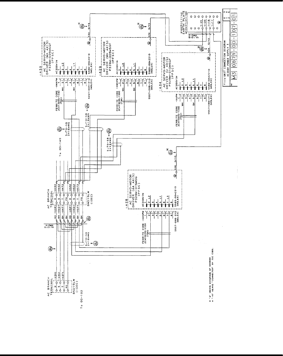
6.3 Power Source Circuit Diagram
SERVICE MANUAL
AVK3
6.3−7
D76SEC−85−190−A0

6.3 Power Source Circuit Diagram
SERVICE MANUAL
AVK3
6.3−8
D76SEC−85−190−A0
6.4 ROM Parameter List
SERVICE MANUAL
AVK3
6.4−1
D76SEC−85−010−A0
6.4 ROM Parameter List
D76SEC−85−010−A0
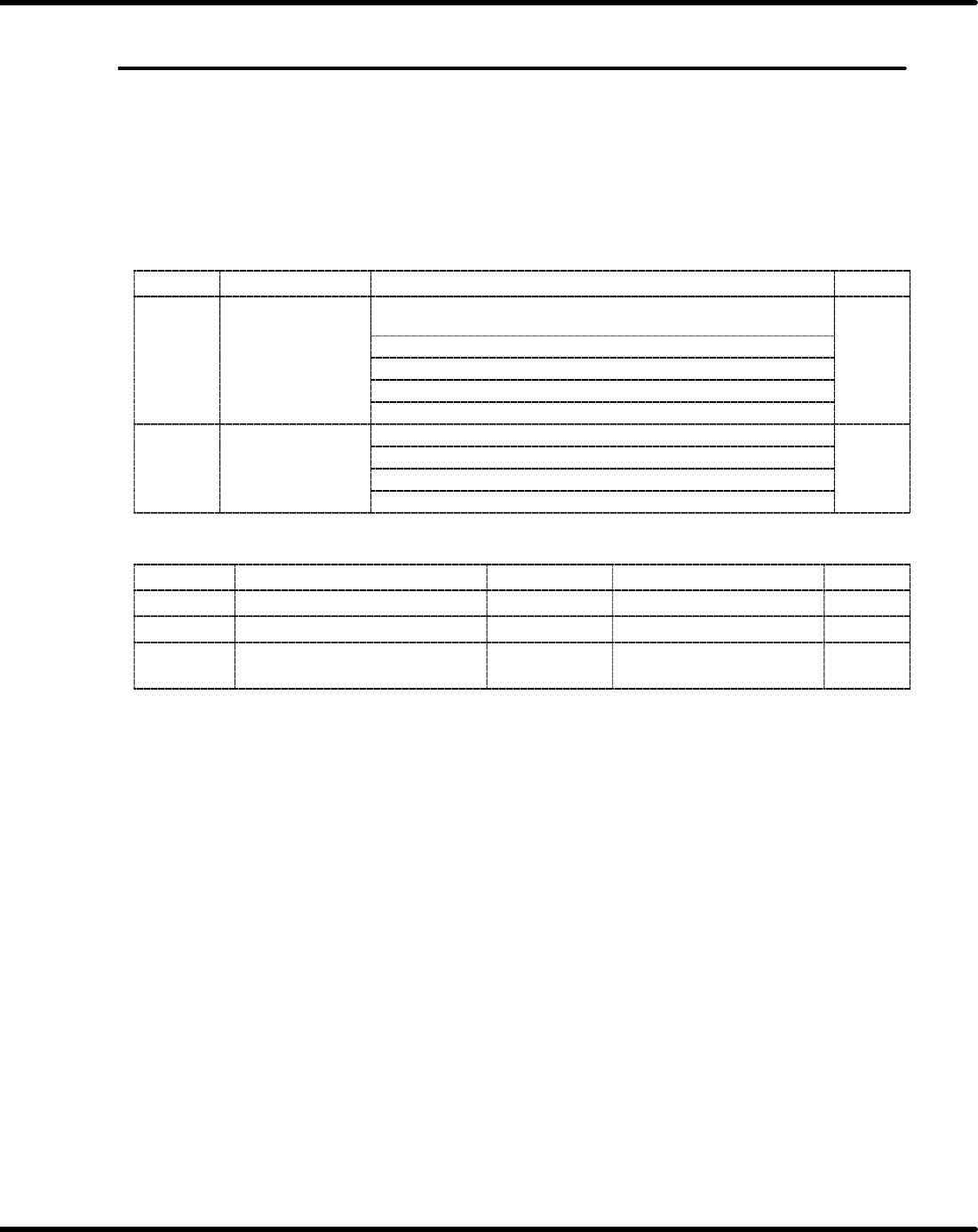
Sentence No.
Composition of parameter
=NOTE=
The following settings are based on machines shipped and might change according to
the software version−up.
MMC
Address
Contents Definition Default
Si l
t
0 : Blinking yellow (parts lack of one axis),
Lighting yellow (parts lack of both axes)
021E
Signal tower
lighting
condition
1 : Blinking yellow (parts lack)
2
021E
lighting condition
1
2 : Standard
2
1
3 : Lighting yelloe and red (parts lack)
4 : Blinking yellow (parts lack)
Signal
tower
0 : Lighting red (PCB standby and scheduled production termination)
021F
Signal tower
lighting
condition
1 : Lighting yellow (PCB standby)
3
021F
li
g
h
t
i
ng con
di
t
i
on
2
2 : Not light or blink (scheduled production termination)
3
2
3 : Standard
MMI
Address Contents Label Definition Default
7FE98 Auto rail width control
00h : Invalid 01 : Valid
00
7FE9A Password
00h : Invalid 01 : Valid
01
7FE9E
Inserting component of 1 mm
in lead diameter
00h : Invalid 01 : Valid
00