_414214_AVK3 服务手册.pdf - 第53页
4.2 Axis Origin Adjustment SERVICE MANUAL A VK3 4.2−2 D77SEC−83−1Z0−A0 = MEMO =
4.2 Axis Origin Adjustment
SERVICE MANUAL
AVK3
4.2−1
D77SEC−83−1Z0−A0
4.2 Axis Origin Adjustment
D77SEC−83−1Z0−A0
Sentence No.
4.2 Axis Origin
Adjustment
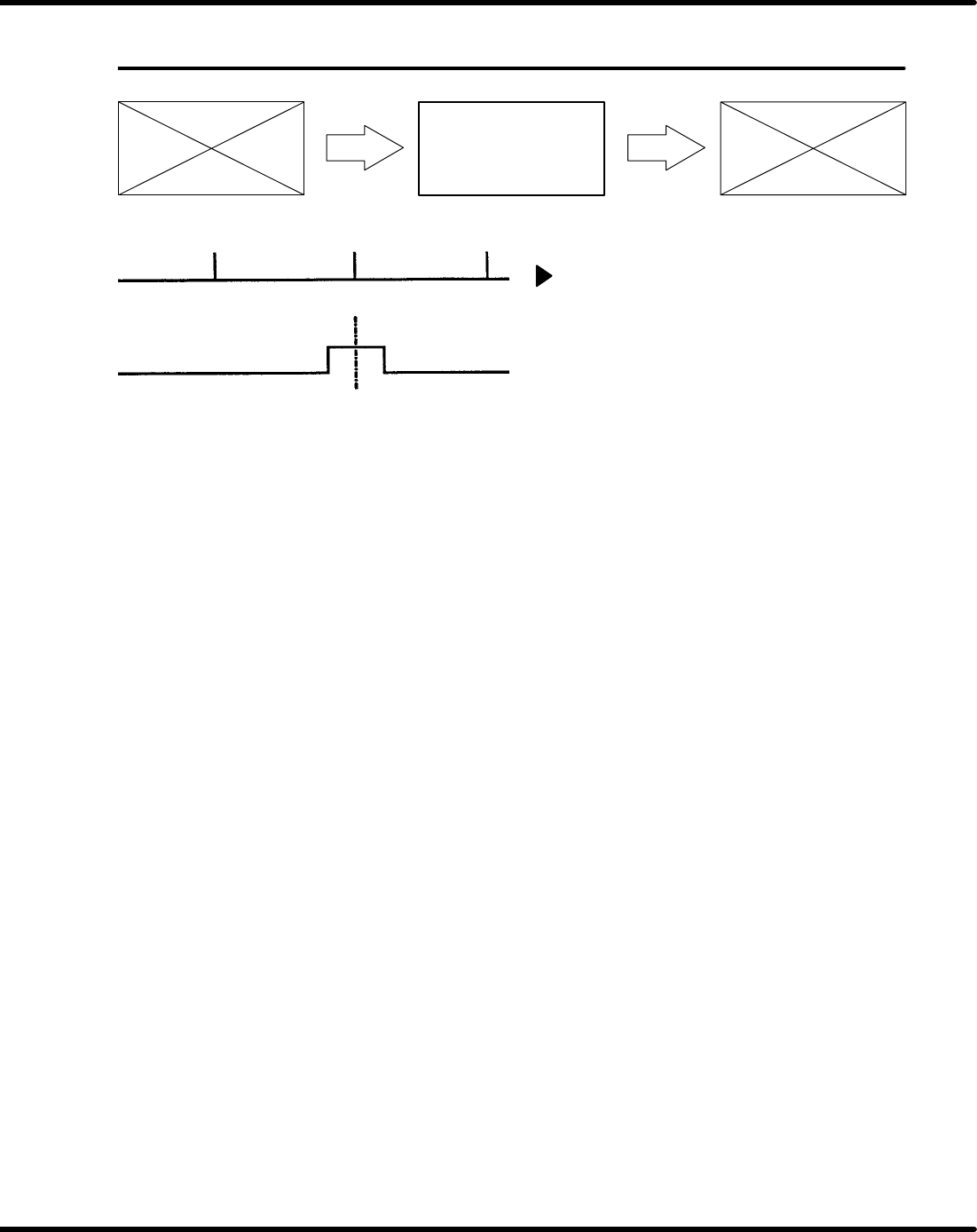
Motor origin
Origin sensor
Origin ← One motor rotation → Origin
←
One motor rotation → Origin
=Preparation=
1. Vinyl tape
Axis origin adjustment
1. Turn the power [ON].
2. Loosen the N coupling fixing the axis or
one side (the driving side) of the cotter.
=NOTE=
Make sure that the motor and N
coupling or the cotter is in the
locked state, and the driving axis
lightly rotates.
3. Short-circuit t he origin sensor or shield
with the vinyl tape to set it to come [ON].
4. Return to origin.
5. Move the driving side until the sensor dog
is the center of the origin sensor.
6. Tighten the N coupling or the cotter.
7. Take the vinyl tape out from the origin
sensor.
8. Check the sensor position.
=NOTE=
Be sure to fasten the origin sensor
to meet the center of the sensor dog
and the center of the sensor.(Check
for symmetrical positioning.)
=NOTE=
There is no slow down sensor.
Manual origin return moves at slow
speed and auto origin return moves
at high speed (pulse count move-
ment).

4.2 Axis Origin Adjustment
SERVICE MANUAL
AVK3
4.2−2
D77SEC−83−1Z0−A0
= MEMO =
4.3 XY Table Origin Check
SERVICE MANUAL
AVK3
4.3−1
D77SEC−83−D00−A0
4.3 XY Table Origin Check
D77SEC−83−D00−A0
Sentence No.
4.4 XY Table Overlimit
Adjustment
4.3 XY Table Origin
Check
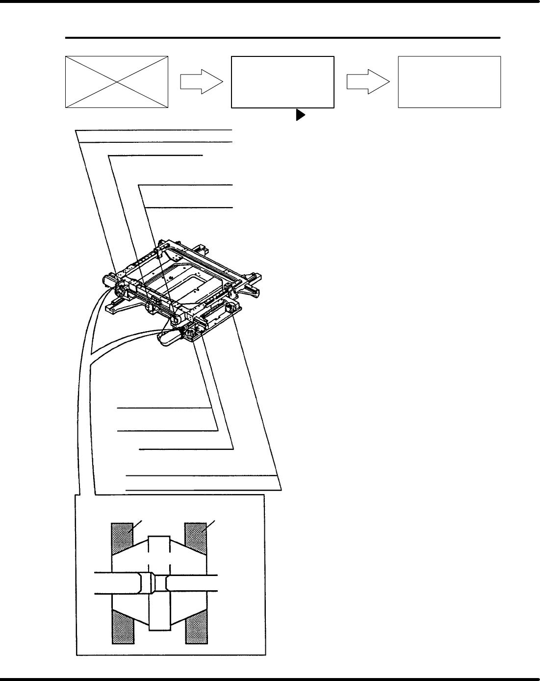
X axis (+) limit sensor
X axis (+) safety limit switch
X axis origin sensor
X axis (−) safety limit switch
X axis (−) limit sensor
Nut D
N cup
Motor axis Ball screw axis
Y axis (+) limit sensor
Y axis (+) safety limit switch
Y axis origin sensor
Y axis (−) safety limit switch
Y axis (−) limit sensor
Nut D
XY table origin check
1. Turn the power [ON].
2. Turn ”SERVO MOTOR” on the main con-
trol panel [OFF] then, open the cover and
move the XY table to any position except
origin.
=NOTE=
Make sure that the LED of the limit
sensor is illuminated.
3. Close the front cover and press ”START”
on the main control panel. (This clears the
safety stop).
4. Press “RESET” on the main control pan-
el and turn “SERVO MOTOR” on the
main control panel [ON].
5. Press “MANU” and “ORG” on the main
control panel.
=NOTE=
Make sure that the asterisks of the
X and Y axes blink on the main con-
trol panel display when XY table re-
turns to origin.
=NOTE=
Be careful of safety, since all axes
will return to their origin.