_414214_AVK3 服务手册.pdf - 第31页
2.1 Installation Procedure SERVICE MANUAL A VK3 2.1−6 D77SEC−1 1−040−A0 Always shut OFF the machine power switch before performing wiring. There is the possibility of electric shock.
2.1 Installation Procedure
SERVICE MANUAL
AVK3
2.1−5
D77SEC−11−040−A0
2.1.4 Safety Check for Factory Power Connections
Power wire check
Before supplying the power from the factory, visually check that the wire insulating sheath has
no damage nor degradation (crack, flaw and others).
Measurement of insulation resistance of the machine
Measure the insulation performance (insulation resistance) of the machine by following the
procedure shown below before connecting the factory power and make sure that it is 5 MΩ or
more.
1. Prepare a measuring instrument of insulation resistance tester which has the capacity of
DC500 V (common name: megger).
2. Make measuring terminal of insulation resistance tester have short circuit and make sure
that it is 0 Ω.
3. Turn ON the machine breaker, the external transformer breaker, the machine power switch,
the external transformer power switch and others.
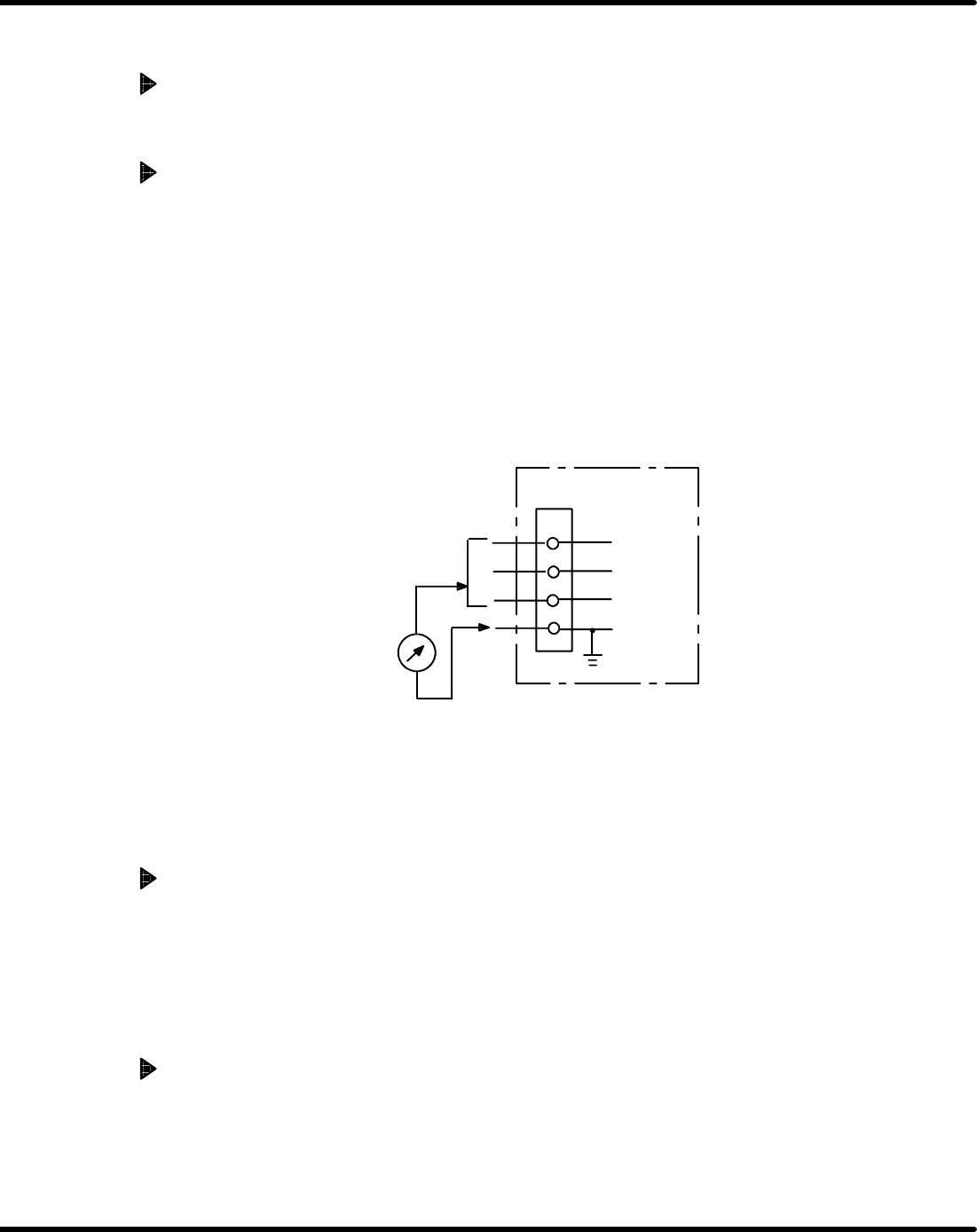
4. Measure the insulation resistance between the machine power wire and the ground wire (PE
wire).
Insulation resistance tester
(Megger)
T
The terminals R, S and T
should be connected.
S
PE
R
Machine
=NOTE=
When the voltage regulator is connected between the machine and factory power,
measure the insulation performance of voltage regulator in the same way as the ma-
chine.
When the insulation performance is out of the criteria
1. Turn OFF the switch which is the farthest from the power side and check the change of the
insulation resistance.
2. Point out the position where the insulation resistance has a big change and check unit/wiring
in detail. Repair the wire if there are some faults.
3. When the problem persists even after re−wiring, component/unit may be defective. Ex-
change or repair the component/unit.
Checks after factory power connection
1. Tell the customers to ask the electrical facility specialist (maintenance provider), who have a
contract with the customers, to measure the insulation performance.

2.1 Installation Procedure
SERVICE MANUAL
AVK3
2.1−6
D77SEC−11−040−A0
Always shut OFF the machine
power switch before performing
wiring.
There is the possibility of
electric shock.
2.1 Installation Procedure
SERVICE MANUAL
AVK3
2.1−7
D77SEC−11−040−A0
2.1.5 Precision, Performance, Operation and Safety
Check
Feeder carriage safety limit operation check
1. Turn power [ON] and turn [OFF] the ”SERVO MOTOR” switch on the main control panel.
2. Check if the feeder carriage (Z axis) sensor dogs interfere with sensors.
3. Check the operation of the (+)safety limit, (−) safety limit and feeder carriage interference
safety limit.
(1) Move the left feeder carriage manually to turn [ON] the (+) safety limit.
(2) Check that the POWER switch on the main control panel is turned [OFF].
(3) Move the left feeder carriage manually to turn [OFF] the (+) safety limit.
(4) Check that the POWER switch on the main control panel is turned [ON].
(5) Check the operation of the (−) safety limit by the same procedures described above.
XY axes safety limit operation check
1. Turn the power [ON] and turn “HEAD SERVO” on the head switches [OFF].
2. Check the operation of the X axis (+), (−) safety limits and the Y axis (+), (−) safety limits.
(1) Move the XY table manually and turn the X axis (+) safety limit [ON].
(2) Check that the POWER switch on the main control panel is turned [OFF].
(3) Move the XY table manually and turn the X axis (+) safety limit [OFF].
(4) Check that the POWER switch on the main control panel is turned [ON].
(5) Check the X axis (−) safety limit and Y axis (+), (−) safety limits by the same procedures
as described above.
Emergency switch operation check
1. Check whether the emergency switch operates correctly in 5 places on the machine front
and rear.
Checking safety cover switches
1. Open and close the main cover and rear cover to check the safety switches for proper func-
tion.