_414214_AVK3 服务手册.pdf - 第25页
SERVICE MANUAL A VK3 2.0−2 D77SEC−1 1−000−A0 = MEMO =

SERVICE MANUAL
AVK3
2.0−1
D77SEC−11−000−A0
D77SEC−11−000−A0
Sentence No.
2. INSTALLATION
2.0(Section2)
This chapter describes information on Panasert installation.
•
Be sure to read ’Safety Precautions’ in this manual carefully.

SERVICE MANUAL
AVK3
2.0−2
D77SEC−11−000−A0
= MEMO =
2.1 Installation Procedure
SERVICE MANUAL
AVK3
2.1−1
D77SEC−11−040−A0
2.1 Installation Procedure
D77SEC−11−040−A0
Sentence No.
2.1.1 Installation Position
Installation position
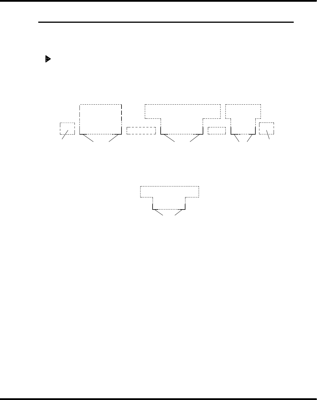
1. Decide the installation position of machines from layout drawing (CAD drawing, etc.).
2. Mark the reference points of each machine on the floor with a marker pen, etc.
=NOTE=
In most cases, the machine front corners are used as reference points.
AVK3
JVK3B
BSF−V
C−CON
MBS
RHSG
C−CON
Reference points Reference points Reference points
*C−CON are connection conveyors which stand between machines.
3. Install the main body of each machine temporarily at reference points. (except for C-CON,
etc.)
4. The installation should start from the heaviest machine (A VK3).
AVK3
Reference points
5. Install the AVK3 main body accurately on reference points.
6. Decide the height from the floor to the transfer belt surface.
=Specification=
Height : 915±5mm
7. Adjust t he machine level (roughly).
8. Install other machines temporarily following the same procedure.
9. Install accessory conveyors such as C-CON, etc..
10. Raise the loader and unloader to the upper limit and adjust the clearance between the rails.
=Specification=
Clearance : 5±2mm
=NOTE=
If approx. 6mm cannot be provided between rails, move the machine.
11. Decide the height from the floor to the transfer belt surface.
=NOTE=
Depending on floor surface, there are times when transfer height can not reach
915mm.
12. Adjust the level between rails (front/rear, up/down directions).