_414214_AVK3 服务手册.pdf - 第43页
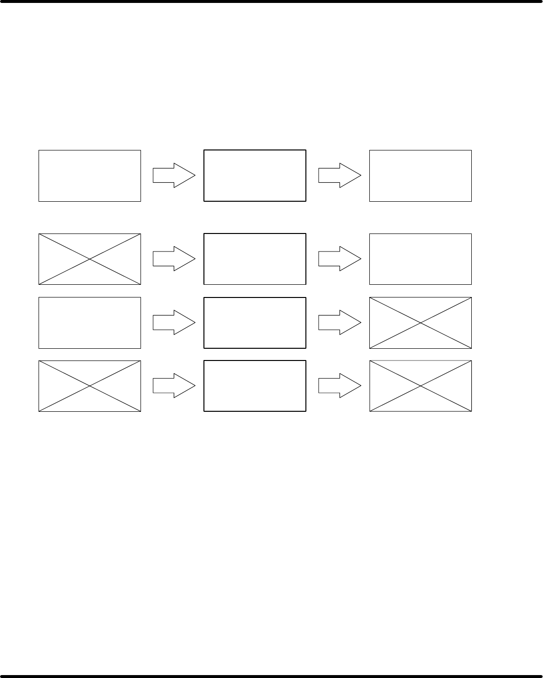
SERVICE MANUAL A VK3 4.0−2 D77SEC−83−000−A0 • Each section has the procedure for performing maintenance as described below . The maintenance of the current page is represented by a bold frame. The left frame shows the ma…

SERVICE MANUAL
AVK3
4.0−1
D77SEC−83−000−A0
D77SEC−83−000−A0
Sentence No.
4.MAINTENANCE GUIDE
(MECHANICAL)
4.0(Section2)
This chapter includes explanations of how to check, adjust and repair when
performing installation, inspection.
•
To avoid personal injury, follow proper maintenance procedures.
•
Be sure to read ’Safety Precautions’ in this manual carefully.
•
Refer to ’Operation Manual’, ’Programming Manual’ and ’Reference
Manual’ from the Operating Instructions for machine operation.
•
Please have the jigs and tools supplied with the machine available.
The ’ =Preparation= ’ section of each procedure does not include these
jigs and tools.
SERVICE MANUAL
AVK3
4.0−2
D77SEC−83−000−A0
•
Each section has the procedure for performing maintenance as
described below.
The maintenance of the current page is represented by a bold frame.
The left frame shows the maintenance that must be done before
performing this maintenance, and the right frame shows the next
maintenance to be done.
Always follow the sequence when performing maintenance.
=NOTE=
Indication of related work in sequence.
=NOTE=
Indication of unrelated and some related work (independent).
4.1 Adjustment Check List
SERVICE MANUAL
AVK3
4.1−1
D77SEC−83−010−A0
4.1 Adjustment Check List
D77SEC−83−010−A0
Sentence No.
No. Adjustment Item Check
Refer-
ence
T
ransformer
V
oltage
AC 100V
T
rans
f
ormer
V
o
lt
age
AC 200V
Connector looseness
+5.00 to +5.25V
P783
+12.00 to +12.60V
Electrical
P783
main controller
Voltage
−12.00 to −12.60V
1.
El
ectr
i
ca
l
control sys-
tem
+15.00 to +15.75V
t
em
−15.00V to −15.75V
AC servo motor drivers Connector looseness
Power
supplier
Volta
g
e
5.1 to 5.6V
P
ower supp
li
er
V
oltage
(internal)
23.5 to 25.5V
Cooling
fan
Motor Normal rotation
C
oo
li
ng
f
an
Filter Clogging, dirt
Pneumatic
0.5MPa
Pneumatic
Main
regulator
P
neuma
ti
c
pressure
Stability during opera-
tion
2.
P
neumat
i
c
pressure con-
trol system
M
a
i
n regu
l
a
t
or
Pressure
switch
0.4MPa
Filter clogging, sediments in bowl
Tubing Wearing, damage, connection looseness