_414214_AVK3 服务手册.pdf - 第57页
4.4 XY T able Overlimit Adjustment SERVICE MANUAL A VK3 4.4−2 D77SEC−83−2A0−A0 = MEMO =
4.4 XY Table Overlimit Adjustment
SERVICE MANUAL
AVK3
4.4−1
D77SEC−83−2A0−A0
4.4 XY Table Overlimit Adjustment
D77SEC−83−2A0−A0
Sentence No.
4.4 XY Table Overlimit
Adjustment
4.3 XY Table Origin
Check
Movement area
Safety limit switch
Limit switch
D4B−211N
Bracket (a)
Origin
XY table sensor position
X axis
Y axis
−328.00mm
+23.00mm
+283.00mm
−386.00mm
Attach the sensor so the slit board hits
the sensor optical axis without fail.
Slit board
Optical
axis
Sensor
Bad
Good
Origin
Slit board
=NOTE=
Be sure to do following performance
with the X axis and the Y axis origin
sensors in a matching state, and
with the limit switch in the operating
state.
=NOTE=
The position where bracket (a)
presses the limit switch until there is
a click sound.
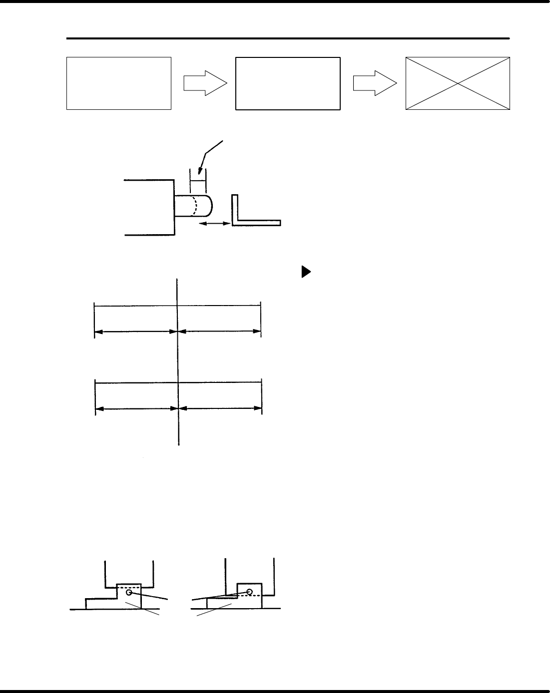
XY table overlimit adjustment
1. Turn the power [ON] and return to origin.
2. Move the XY table in NC AXIS JOG
CHECK and check that the slit board is
not in contact with the sensors.
3. Move the XY table and check the (+), (−)
limit sensors.
=Specification=
X axis overlimit position
(+) limit : 283.00 + 0.1,−0 mm
(−) limit : −328.00 + 0, −0.1mm
Y axis overlimit position
(+) limit : 23.00 + 0.1,−0 mm
(−) limit : −386.00 + 0, −0.1mm
4. If not within the specification, adjust the
sensor bracket position and check again.

4.4 XY Table Overlimit Adjustment
SERVICE MANUAL
AVK3
4.4−2
D77SEC−83−2A0−A0
= MEMO =

SERVICE MANUAL
AVK3
5.0−1
D77SEC−84−000−A0
D77SEC−84−000−A0
Sentence No.
5. MAINTENANCE GUIDE
(CONTROLS)
5.0(Section2)
This chapter includes explanations about adjustment procedures which are
related to control system.
•
Improper machine operation could result in personal injury.
•
Be sure to read “Safety Precautions” in this manual carefully.