_414214_AVK3 服务手册.pdf - 第62页
5.1 AC Servo Gain Adjustment SERVICE MANUAL A VK3 5.1−3 D77SEC−84−040−A0 3. Make the gain adjustment program. Refer to following table. Gain adjustment program settings : Axis T ravel distance X, Y 2.5, 5.0, 7.5, 10.0, 1…
5.1 AC Servo Gain Adjustment
SERVICE MANUAL
AVK3
5.1−2
D77SEC−84−040−A0
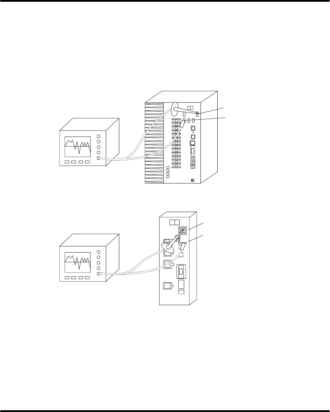
1. Supply the power to oscilloscope not from the machine AVK3 but from another which is un-
connected to AVK3.
2. Attach oscilloscope probe to ’PERM’ and ’GND’ of the motor driver monitor terminal.
PERM
GND
PERM
GND
Oscilloscope
Oscilloscope
P326M (H axis, θH axis, ZL axis and ZR axis)
P326M(X axis, Y axis, WH axis, WA axis, U axis, θA axis,
T axis and V axis)
5.1 AC Servo Gain Adjustment
SERVICE MANUAL
AVK3
5.1−3
D77SEC−84−040−A0
3. Make the gain adjustment program.
Refer to following table.
Gain adjustment program settings :
Axis Travel distance
X, Y 2.5, 5.0, 7.5, 10.0, 12.5, 15.0, 100.0mm
ZL, ZR 1, 2, 5, 60 cassettes
T 90°
U 5.0, 10.0, 26.0mm
θH 0°, 180°, 270°
θA 0°
WH 5.0, 10.0, 21.0mm (pitch change)
WA 5.0, 10.0, 21.0mm (pitch change)
V
Change from wire diameter 0.6, body diameter 0.6 (Jumper wire)
to wire diameter 0.8, body diameter 5.0.
H At θ = 180°
=NOTE=
Refer to ’Operating Instructions’ to make the gain adjustment program.
4. Execute the program and check the AC servo driver wave by the oscilloscope and the servo
motor condition.
5. Select “F8” → “F1” (MACHINE INITIAL SETTINGS) →“F3” (PRODUCTION CON-
DITIONS SETTING) → “F6” → “G” → “A” → “I” → “N” → “F6” from the service menu
screen of main control panel.
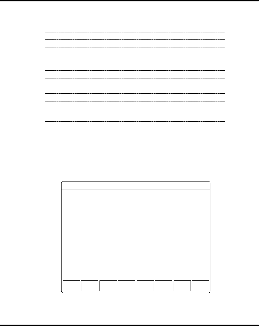
6. The menu screen appears on the monitor screen as follows,
<F1> <F2> <F3> <F4> <F5> <F6> <F7> <F8>
YYYY − MM − DD HH : MM
SELECT FUNCTION KEY.
MANUAL : 1 BLOCK << M/C INI. VAL. SET >>
RETURN
TO DISP
F1.
F2.
F3.
F4.
F5.
F6.
F7.
F8.
MOVEMENT DRIVER GAIN SETTING
STOPPING DRIVER GAIN SETTING
RETURN TO DISPLAY
DRIVER GAIN SETTING
MOVEMENT
GAIN
STOPPING
GAIN
Figure 5.1−1:Driver Gain Setting
7. Select “F1” (MOVEMENT DRIVER GAIN SETTING).

5.1 AC Servo Gain Adjustment
SERVICE MANUAL
AVK3
5.1−4
D77SEC−84−040−A0
8. Select the OPTICAL LOOP which include adjusting axis.
<F1> <F2> <F3> <F4> <F5> <F6> <F7> <F8>
YYYY − MM − DD HH : MM
SELECT FUNCTION KEY.
MANUAL : 1 BLOCK << M/C INI. VAL. SET >>
RETURN
TO DISP
F1.
F2.
F3.
F4.
F5.
F6.
F7.
F8.
OPTICAL LOOP 1 SETTING (X, Y, ZL, ZR AXIS)
OPTICAL LOOP 2 SETTING (T, U, H, θH AXIS)
RETURN TO DISPLAY
MOVEMENT DRIVER GAIN SETTING
OPTICAL
LOOP 1
OPTICAL
LOOP 2
OPTICAL LOOP 3 SETTING (θA, WH, WA, V AXIS)
OPTICAL
LOOP 3
Figure 5.1−2:Movement Driver Gain Setting
9. Select the adjusting axis.
<F1> <F2> <F3> <F4> <F5> <F6> <F7> <F8>
YYYY − MM − DD HH : MM
SELECT FUNCTION KEY.
MANUAL : 1 BLOCK << M/C INI. VAL. SET >>
RETURN
TO DISP
F1.
F2.
F3.
F4.
F5.
F6.
F7.
F8.
X AXIS
Y AXIS
RETURN TO DISPLAY
OPTICAL LOOP 1 SETTING
X AXIS Y AXIS
ZL AXIS
ZL AXIS
ZR AXIS
PRINT OPTICAL LOOP 1 SETTING
PRINTZR AXIS
X AXIS 2 (EXTRA)
Y AXIS 2 (EXTRA)
X AXIS 2
(EXTRA)
Y AXIS 2
(EXTRA)
Figure 5.1−3:Optical Loop 1 Setting