_414214_AVK3 服务手册.pdf - 第55页
4.3 XY T able Origin Check SERVICE MANUAL A VK3 4.3−2 D77SEC−83−D00−A0 = MEMO =
4.3 XY Table Origin Check
SERVICE MANUAL
AVK3
4.3−1
D77SEC−83−D00−A0
4.3 XY Table Origin Check
D77SEC−83−D00−A0
Sentence No.
4.4 XY Table Overlimit
Adjustment
4.3 XY Table Origin
Check
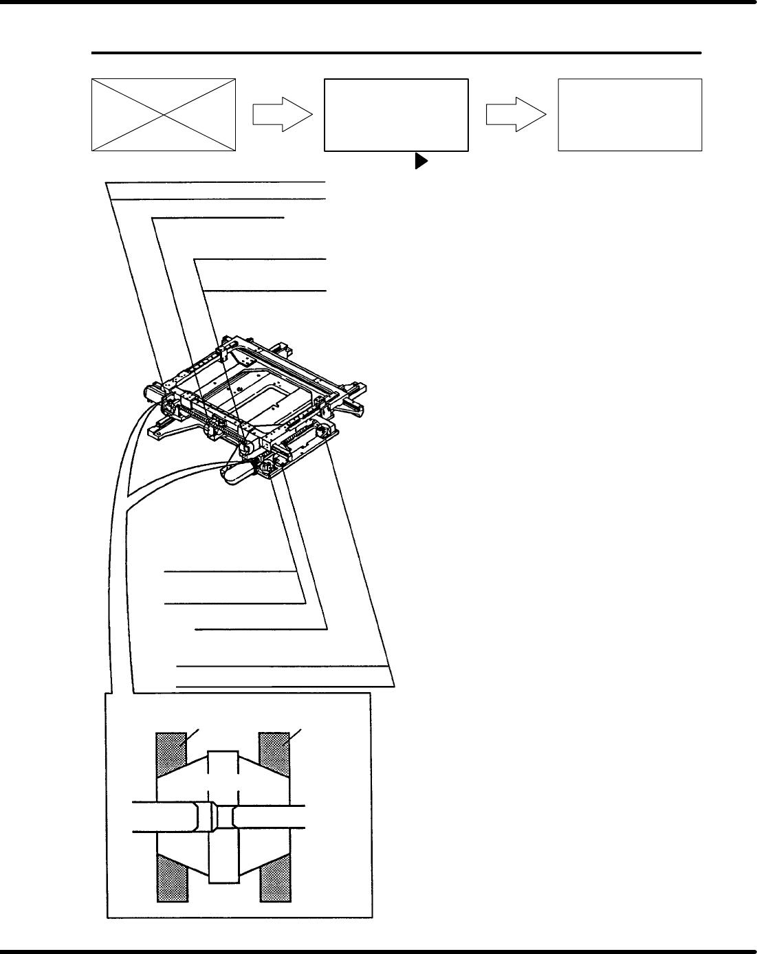
X axis (+) limit sensor
X axis (+) safety limit switch
X axis origin sensor
X axis (−) safety limit switch
X axis (−) limit sensor
Nut D
N cup
Motor axis Ball screw axis
Y axis (+) limit sensor
Y axis (+) safety limit switch
Y axis origin sensor
Y axis (−) safety limit switch
Y axis (−) limit sensor
Nut D
XY table origin check
1. Turn the power [ON].
2. Turn ”SERVO MOTOR” on the main con-
trol panel [OFF] then, open the cover and
move the XY table to any position except
origin.
=NOTE=
Make sure that the LED of the limit
sensor is illuminated.
3. Close the front cover and press ”START”
on the main control panel. (This clears the
safety stop).
4. Press “RESET” on the main control pan-
el and turn “SERVO MOTOR” on the
main control panel [ON].
5. Press “MANU” and “ORG” on the main
control panel.
=NOTE=
Make sure that the asterisks of the
X and Y axes blink on the main con-
trol panel display when XY table re-
turns to origin.
=NOTE=
Be careful of safety, since all axes
will return to their origin.

4.3 XY Table Origin Check
SERVICE MANUAL
AVK3
4.3−2
D77SEC−83−D00−A0
= MEMO =
4.4 XY Table Overlimit Adjustment
SERVICE MANUAL
AVK3
4.4−1
D77SEC−83−2A0−A0
4.4 XY Table Overlimit Adjustment
D77SEC−83−2A0−A0
Sentence No.
4.4 XY Table Overlimit
Adjustment
4.3 XY Table Origin
Check
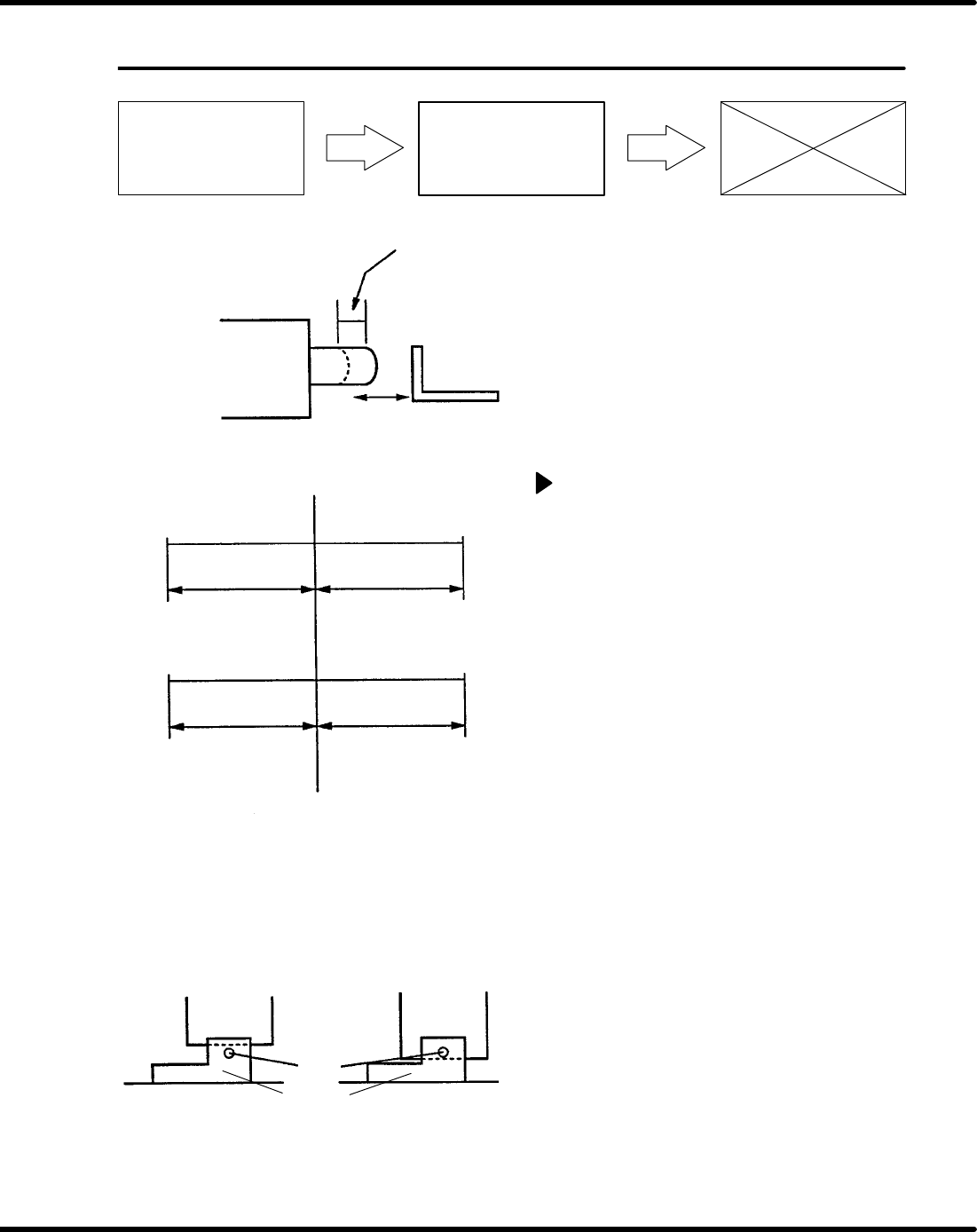
Movement area
Safety limit switch
Limit switch
D4B−211N
Bracket (a)
Origin
XY table sensor position
X axis
Y axis
−328.00mm
+23.00mm
+283.00mm
−386.00mm
Attach the sensor so the slit board hits
the sensor optical axis without fail.
Slit board
Optical
axis
Sensor
Bad
Good
Origin
Slit board
=NOTE=
Be sure to do following performance
with the X axis and the Y axis origin
sensors in a matching state, and
with the limit switch in the operating
state.
=NOTE=
The position where bracket (a)
presses the limit switch until there is
a click sound.
XY table overlimit adjustment
1. Turn the power [ON] and return to origin.
2. Move the XY table in NC AXIS JOG
CHECK and check that the slit board is
not in contact with the sensors.
3. Move the XY table and check the (+), (−)
limit sensors.
=Specification=
X axis overlimit position
(+) limit : 283.00 + 0.1,−0 mm
(−) limit : −328.00 + 0, −0.1mm
Y axis overlimit position
(+) limit : 23.00 + 0.1,−0 mm
(−) limit : −386.00 + 0, −0.1mm
4. If not within the specification, adjust the
sensor bracket position and check again.