_414214_AVK3 服务手册.pdf - 第49页
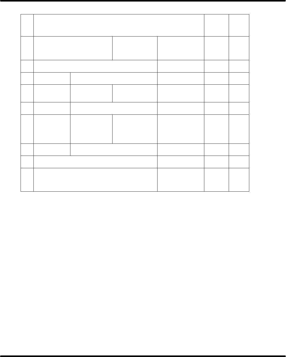
4.1 Adjustment Check List SERVICE MANUAL A VK3 4.1−6 D77SEC−83−010−A0 No. Adjustment Item Check Refer- ence 25. Center of slide block and chuck CT : 236 ° to 291 ° Both centers match. (Visual check) 26. Clearance between…
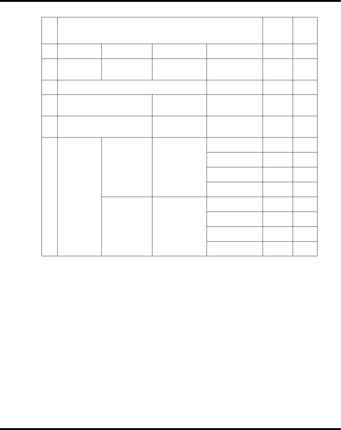
4.1 Adjustment Check List
SERVICE MANUAL
AVK3
4.1−5
D77SEC−83−010−A0
No.
Adjustment Item Check
Refer-
ence
19. Rotary chuck Parallelism CT : 353° to 358° ± 0.02 mm *10
20. Slide chuck
Insertion unit
clearance
CT:83° to 83° 0.4 ± 0.05 mm *11
21. Clearance between scrap duct and guide rail 1.5 to 2.0 mm
22.
Manual operation of rotary
chuck
CT:0°
Rotate smoothly
manually
23.
Center of slider and insertion
unit
Distance from LM
guide
75.47
to 75.53 mm
*12
Chuck 1
Traverse
CT
:127
°
to
995
to10 05
mm
Chuck 2
CT
:
127
°
t
o
197°
9
.
95
t
o
10
.
05
mm
Chuck 3
24
Rotary chuck
traverse
and
Chuck 4
24
.
t
raverse an
d
return stroke
Chuck 1
Return
525
to
535
mm
Chuck 2
Return
CT :220° to 282°
5
.
25
t
o
5
.
35
mm
Chuck 3
Chuck 4
=NOTE=
*10 : Maintenance Manual / MAINTENANCE GUIDE /
Rotary Chuck (T Axis) Unit Adjustment
*11 : Maintenance Manual / MAINTENANCE GUIDE /
Slide Chuck Stroke Adjustment
*12 : Maintenance Manual / MAINTENANCE GUIDE /
T axis and Insertion Unit Adjustment
4.1 Adjustment Check List
SERVICE MANUAL
AVK3
4.1−6
D77SEC−83−010−A0
No.
Adjustment Item Check
Refer-
ence
25. Center of slide block and chuck CT : 236° to 291°
Both centers
match. (Visual
check)
26. Clearance between slider and roller floor No clearance
27. Slide block Backlash with lead screw No backlash
28. Tape cutter
Thrust in
amount
CT : 324° 0.1 to 0.2mm *13
29. Cutter blade Alignment 0to0.1mm
30.
Transfer
chuck
Z axis position CT : 197° to 220°
Check V groove
matches with part
position.(Visual
check)
31. ZR Offset −1.67 to 1.67mm
32. Clearance between reference lever and guide rail 0.45 to 0.55mm
33. Center of transfer pin and reference pin
Both centers
match. (Visual
check)
=NOTE=
*13 : Maintenance Manual / MAINTENANCE GUIDE / Tape Cutter Replacement
4.1 Adjustment Check List
SERVICE MANUAL
AVK3
4.1−7
D77SEC−83−010−A0
No.
Adjustment Item Check
Refer-
ence
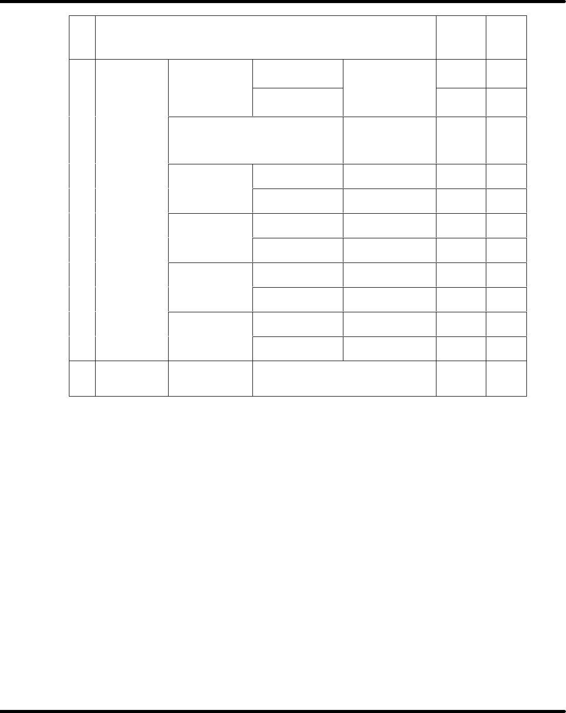
Rail
height
Loader
The height of fixed
rail and movable
R
a
il
h
e
i
g
ht
Unloader
rail
and
movable
rail are same.
(Visual check)
Traverse and return timing of loader
and unloader
Check the timing
is synchronizing
(Visual check)
Rail
parallelism
Loader rail 0to0.5mm
34.
T
ransfer
unit
R
a
il
para
ll
e
li
sm
Unloader rail 0to0.5mm
34
.
T
ransfer
unit
Parallelism with
Loader rail 0to0.3mm
Parallelism
with
XY table
Unloader rail 0to0.3mm
Hei
g
ht with XY
Loader rail 0to0.3mm
Height
with
XY
table
Unloader rail 0to0.3mm
Clearance with
Loader rail 1to3mm
Clearance
with
XY table
Unloader rail 1to3mm
35. Camera Camera image
Make sure there is no foreign matter
within the camera image.