_414214_AVK3 服务手册.pdf - 第72页
5.1 AC Servo Gain Adjustment SERVICE MANUAL A VK3 5.1−13 D77SEC−84−040−A0 1. Change the movement gain setting values according to the following table. =NOTE= The values of “Feed forward” should be the standard values. Mo…
5.1 AC Servo Gain Adjustment
SERVICE MANUAL
AVK3
5.1−12
D77SEC−84−040−A0
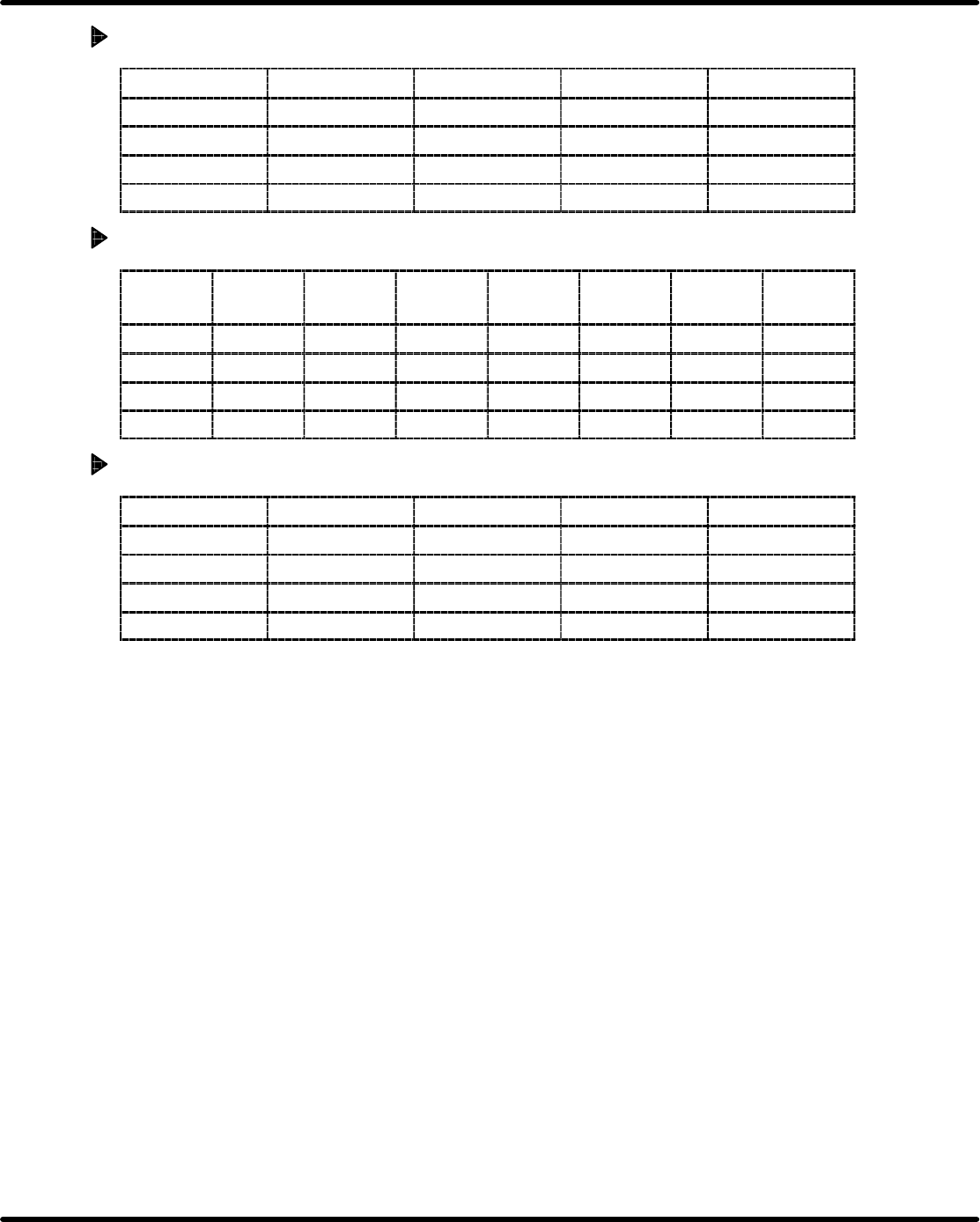
WA Axis Stop Gain
posi prorl speed prorl speed integra change time
POST1 16 20 0 0
ORIGIN 10 12 0 0
TCH(L) 10 10 0 0
TCH(H) 10 10 0 0
V Axis Move Gain
distance
high
speed
accelerate
posi prorl
speed
prorl
speed
integra
feed forward
POST1 0.00 ∼ 6668 1500 10 2 10 0
ORIGIN − 500 250 5 3 8 5
TCH(L) − 38 25 2 5 8 5
TCH(H) − 250 100 1 5 8 5
V Axis Stop Gain
posi prorl speed prorl speed integra change time
POST1 10 1 25 0
ORIGIN 3 2 2 8
TCH(L) 5 2 2 8
TCH(H) 5 2 2 8
5.1 AC Servo Gain Adjustment
SERVICE MANUAL
AVK3
5.1−13
D77SEC−84−040−A0
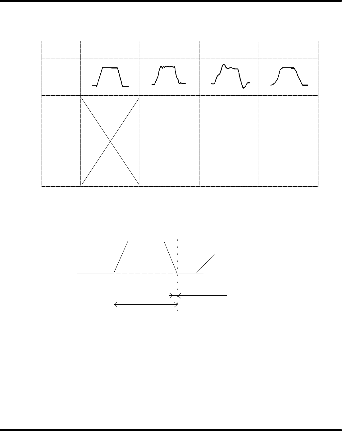
1. Change the movement gain setting values according to the following table.
=NOTE=
The values of “Feed forward” should be the standard values.
Motor
condition
Ideal Noisy
Not smooth
movement
Bad positioning
precision
Wave
Adjust-
ment pro-
cedure
1. Reduce the
speed feedback.
2. Reduce the
integral of speed.
3. Reduce the posi-
tional feedback.
1. Reduce the posi-
tional feedback.
2. Reduce the
speed feedback.
3. Reduce the
integral of speed.
1. Reduce the posi-
tional feedback.
2. Reduce the
speed feedback.
3. Reduce the
integral of speed.
Movement gain
adjustable area
Stopping gain
adjustable area
AC servo driver wave
(Oscilloscope)
2. Execute the program and compare the motor wave and the ideal wave.
3. If the wave is bad shape, adjust the gain again.
=NOTE=
AC servo gain should be adjusted only by changing the movement gain setting values.
5.1 AC Servo Gain Adjustment
SERVICE MANUAL
AVK3
5.1−14
D77SEC−84−040−A0
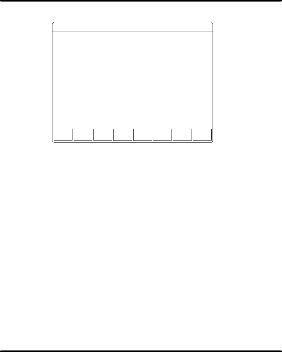
4. If the wave is still bad shape, back to the following screen and select “F2” (STOPPING
DRIVER GAIN SETTING).
<F1> <F2> <F3> <F4> <F5> <F6> <F7> <F8>
YYYY − MM − DD HH : MM
SELECT FUNCTION KEY.
MANUAL : 1 BLOCK << M/C INI. VAL. SET >>
RETURN
TO DISP
F1.
F2.
F3.
F4.
F5.
F6.
F7.
F8.
MOVEMENT DRIVER GAIN SETTING
STOPPING DRIVER GAIN SETTING
RETURN TO DISPLAY
DRIVER GAIN SETTING
MOVEMENT
GAIN
STOPPING
GAIN
5. Change the stopping gain setting values with the same procedures as the movement gain.
=NOTE=
The values of ’Change time’ should be standard values.
6. Execute the program and check the motor wave.