IPC-SM-782A 表面安装设计和焊盘设计标准(带BGA).pdf - 第218页
4.0 COMPONENT DIMENSIONS Figure 1 provides the component dimensions for rectangular PBGAs. Component ABCD W P H F G Identifier max max max max nom. basic max nom. nom. R-PBGA 22x14 14.00 22.00 7.62 20.32 0.75 1.27 3.50 3.…

1.0 SCOPE
This subsection provides the component and land pattern
dimensions for rectangular 1.27 mm pitch Plastic Ball Grid
Arrays (PBGA).
2.0 APPLICABLE DOCUMENTS
The following documents, of the issue in effect on the current
revision date of this section, form a part of this specification to
the extent specified herein.
2.1 Joint Electronic Device Engineering Council
1
JEDEC Publication 95 Registered and Standard Outlines for
Solid State and Related Products:
• Rectangular Plastic Ball Grid Array (R-PBGA), MS-028
3.0 COMPONENT DESCRIPTION
These components are all on 1.27 mm pitch. They are avail-
able in a wide variety of body sizes. The data supplied in the
detail and table reflect a full matrix. Specific contact and
depopulation and pin assignment must be furnished by the
device manufacturer (see Section 14.0 for more information
on depopulation methods).
1. JEDEC: 2500 Wilson Blvd., Arlington, VA, 22201-3834, USA.
IPC-SM-782
Surface Mount Design
and Land Pattern Standard
Date
4/99
Section
14.2
Revision
—
Subject
1.27 mm Pitch
Rectangular PBGA
JEDEC MS-028
Page1of4
电子技术应用 www.ChinaAET.com
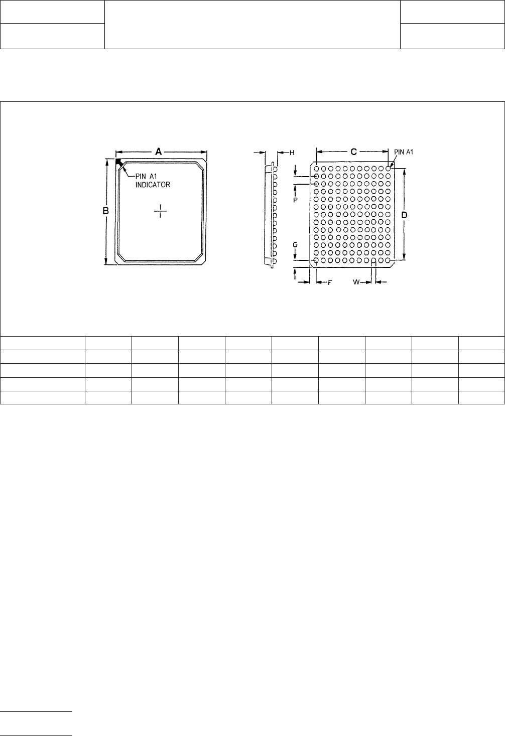
4.0 COMPONENT DIMENSIONS
Figure 1 provides the component dimensions for rectangular PBGAs.
Component ABCDWPHFG
Identifier max max max max nom. basic max nom. nom.
R-PBGA 22x14 14.00 22.00 7.62 20.32 0.75 1.27 3.50 3.19 0.84
R-PBGA 22x14 14.00 22.00 10.16 20.32 0.75 1.27 3.50 1.92 0.84
R-PBGA 25x21 21.00 25.00 12.70 22.86 0.75 1.27 3.50 4.15 1.07
FE = Full Even Matrix
FO = Full Odd Matrix
Figure 1 R-PBGA component dimensions
IPC-SM-782
Subject
1.27 mm Pitch Rectangular PBGA JEDEC MS-028
Date
4/99
Section
14.2
Revision
—
Page2of4
电子技术应用 www.ChinaAET.com
5.0 LAND PATTERN DIMENSIONS
Figure 2 provides the land pattern dimensions for square
PBGA components. These numbers represent industry con-
sensus on the best dimensions based on empirical knowledge
of fabricated land patterns.
Note: The data supplied in the detail and table reflect a full
matrix. Specific contact and depopulation and pin assignment
must be furnished by the device manufacturer.
The dotted line in Figure 2 shows the grid placement court-
yard which is the area required to place land patterns and
their respective components in adjacent proximity without
interference or shorting. Numbers in the table represent the
number of grid elements (each element is 0.5 by 0.5 mm) in
accordance with the international grid detailed in IEC publica-
tion 97.
RLP Component Identifier
Contact
Array
Rows x
Cols.
Contact
Count C D X E
Placement
Grid
1080 R-PBGA 22x14 17x7 119 7.62 20.32 0.60 1.27 46X30
1081 R-PBGA 22x14 17x9 153 10.16 20.32 0.60 1.27 46X30
1082 R-PBGA 25x21 19x11 209 12.70 22.86 0.60 1.27 52X44
FE = Full Even Matrix
FO = Full Odd Matrix
For land pattern tolerance analysis,
see Section 14.0, Subsection 6.
Figure 2 R-PBGA land pattern dimensions
IPC-SM-782
Subject
1.27 mm Pitch Rectangular PBGA JEDEC MS-028
Date
4/99
Section
14.2
Revision
—
Page3of4
电子技术应用 www.ChinaAET.com