IPC-SM-782A 表面安装设计和焊盘设计标准(带BGA).pdf - 第51页
IPC-782-4-10 Figure 4–10 Leadless chip carriers with castellated terminations—joint description W = Castellation Width H = Castellation Height P = Land Length External to Package Side Overhang Side Overhang H ▼ ▼ ▼ A ▼ ▼…
IPC-782-4-8
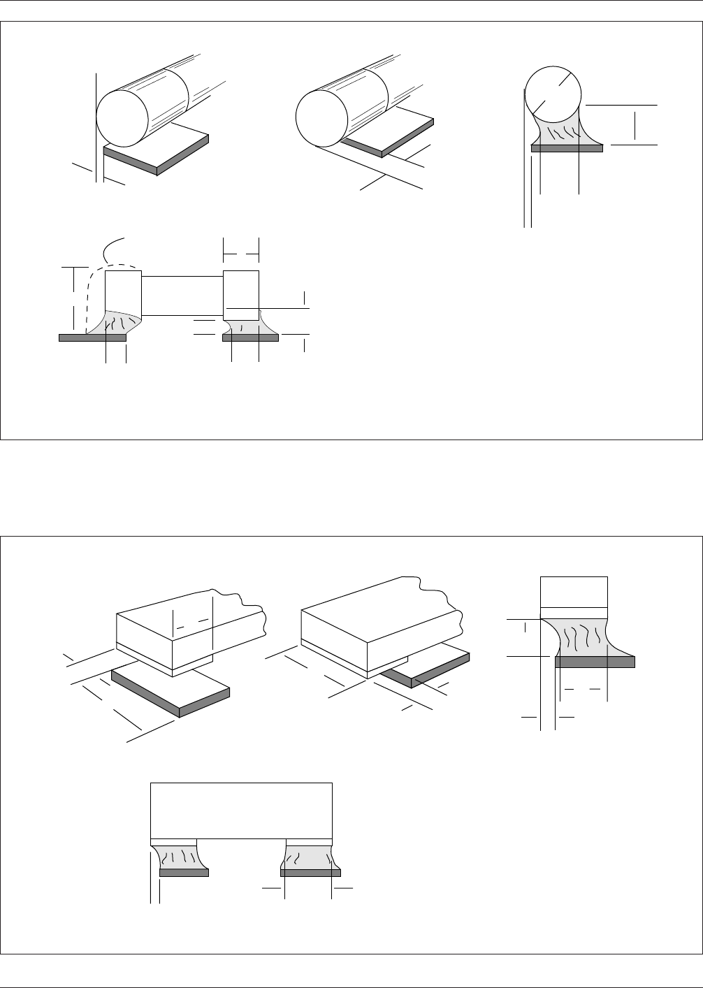
Figure 4–8 Cylindrical end cap terminations—joint illustration
W = Diameter of
Termination
T = Termination/Plating
Length
A
Side
Overhang
▼
See Note 1
Table 9-6
End
Overhang Is
Not Acceptable
▼
▼
B
C
F
A
End
Joint Width
▼
▼
▼
▼
▼
E
▼
▼
T
D
▼
▼
F
Side Joint Length
and End Overlap
▼
▼
J
▼
▼
▼
▼
▼
▼
G
▼
▼
W
▼
▼
▼
IPC-782-4-9
Figure 4–9 Bottom only terminations
C
A
▼
▼
End Joint Width
▼
G
▼
▼
W = Termination Width
T = Termination Length
P = Land Width
End Overhang
Is Not Acceptable
Side
Overhang
▼
▼
W
▼
A
▼
▼
▼
Side Joint Length
G
▼
▼
D
▼
▼
▼
▼
P
T
▼
B
▼
▼
▼
▼
B
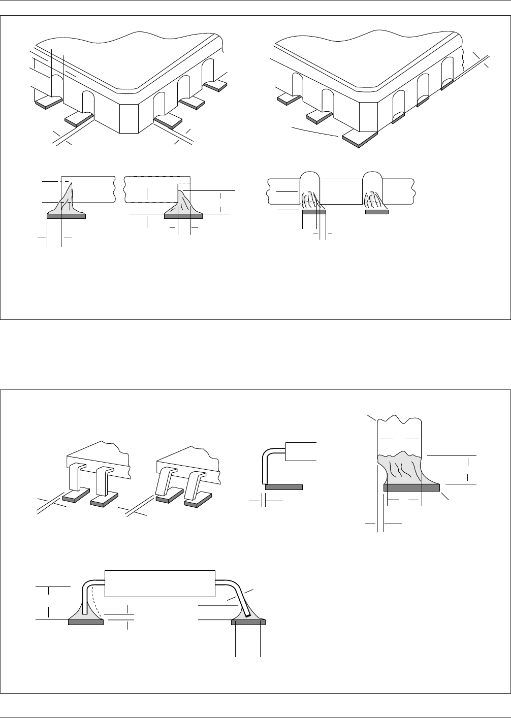
Note: See ANSI/J-STD-001 for specific details on minimum acceptability requirements.
IPC-SM-782A December 1999
42
电子技术应用 www.ChinaAET.com
IPC-782-4-10
Figure 4–10 Leadless chip carriers with castellated terminations—joint description
W = Castellation Width
H = Castellation Height
P = Land Length External
to Package
Side OverhangSide Overhang
H
▼
▼
▼
A
▼
▼
▼
A
End Joint Width
B
▼
▼
Side Joint Length
G
▼
D
▼
F
▼
▼
▼
▼
F
C
▼
▼
▼
▼
A
▼
▼
H
P
▼
Corner
metallization
(termination)
fillet required if
land is present
▼
W
▼
▼
▼
▼
▼
IPC-782-4-11
Figure 4–11 Butt joint description
W = Lead Width
T = Lead Thickness
Side Overhang
C
A
▼
▼
F
▼
▼
End Joint Width
▼
Toe Overhang
Is Not
Acceptable
W
▼
▼
▼
A
▼
▼
A
▼
▼
B
Side Joint Length
E
▼
▼
T
▼
▼
F
▼
▼
▼
▼
D
Land
▼
Lead
▼
G
▼
▼
▼
▼
See Note 1, Table 9–9.
Note: See ANSI/J-STD-001 for specific details on minimum acceptability requirements.
December 1999 IPC-SM-782A
43
电子技术应用 www.ChinaAET.com
IPC-782-4-12
Figure 4–12 Thermal cycle excursion rate
+ 125°
+ 100°
- 65°
400
Cycles
1000
Cycles
0°C
0°C
30
Minutes
30
Minutes
30
Minutes
30
Minutes
30
Minutes
IPC-SM-782A December 1999
44
电子技术应用 www.ChinaAET.com