IPC-SM-782A 表面安装设计和焊盘设计标准(带BGA).pdf - 第48页
IPC-782-4-4 Figure 4–4 Flat ribbon, ‘‘L,’ ’ and gullwing lead joint description B ▼ ▼ A ▼ Side Overhang Toe Overhang End Joint Width T ▼ ▼ D ▼ ▼ ▼ E G Center Line of "T" D ▼ ▼ E ▼ W = Lead Width T = Lead Thickn…
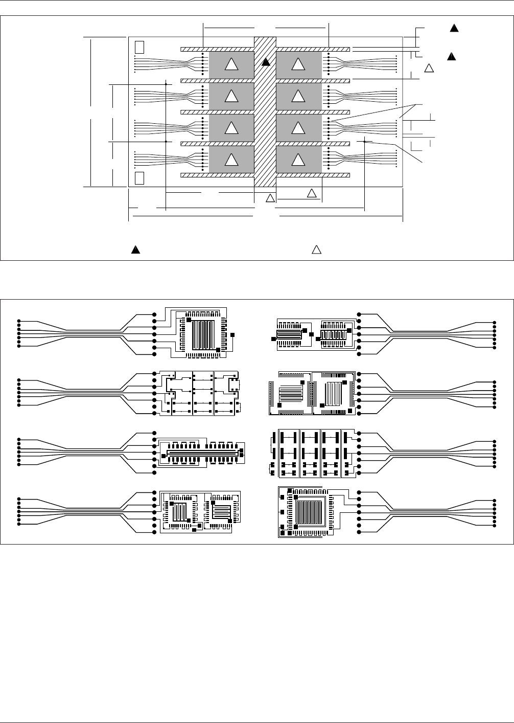
IPC-782-4-2
Figure 4–2 General description of process validation contact pattern and interconnect
5
5
5
5
5
5
5
5
+ 41023 -
+ 1 2 -
4 0 3
+ 41023 -
+ 1 2 -
4 0 3
+ 41023 -
+ 1 2 -
4 0 3
+ 41023 -
+ 1 2 -
4 0 3
+ 14032 -
+ 4 3 -
1 0 2
+ 14032 -
+ 4 3 -
1 0 2
+ 14032 -
+ 4 3 -
1 0 2
+ 14032 -
+ 4 3 -
1 0 2
5.600
▼
▼
▼
▼
I.D.I.D.
2.500
▼
▼
2.125
6.745
▼
▼
1.000
4.010
REF
▼
▼
1.490
▼
▼
4
REF
9.020
▼
▼
4
12 ± 1/32
▼
▼
Note: 1. Board G-10 thickness .040 - .036 2. Primary (top) side
3. Secondary (bottom) side, left-right mirror image
No pattern or components in those
indicated areas allowed 8 sites for test components
5
.505 REF
▼
▼
▼
▼
▼
▼
▼
▼
▼
▼
▼
.140 TYP
1.260
TYP REF
4
5
4
.035 ± .003 DIA,
96 HOLES, PTH
.600 ± .003 TYP
.100 ± .003 TYP
.125 DIA,
3 HOLES
12
3
4
56 7
8
4
2.000 REF
5
▼
▼
▼
▼
▼
All dimensions are in inches
IPC-782-4-3
Figure 4–3 Photo image of IPC-A-49 test board for primary side
December 1999 IPC-SM-782A
39
电子技术应用 www.ChinaAET.com
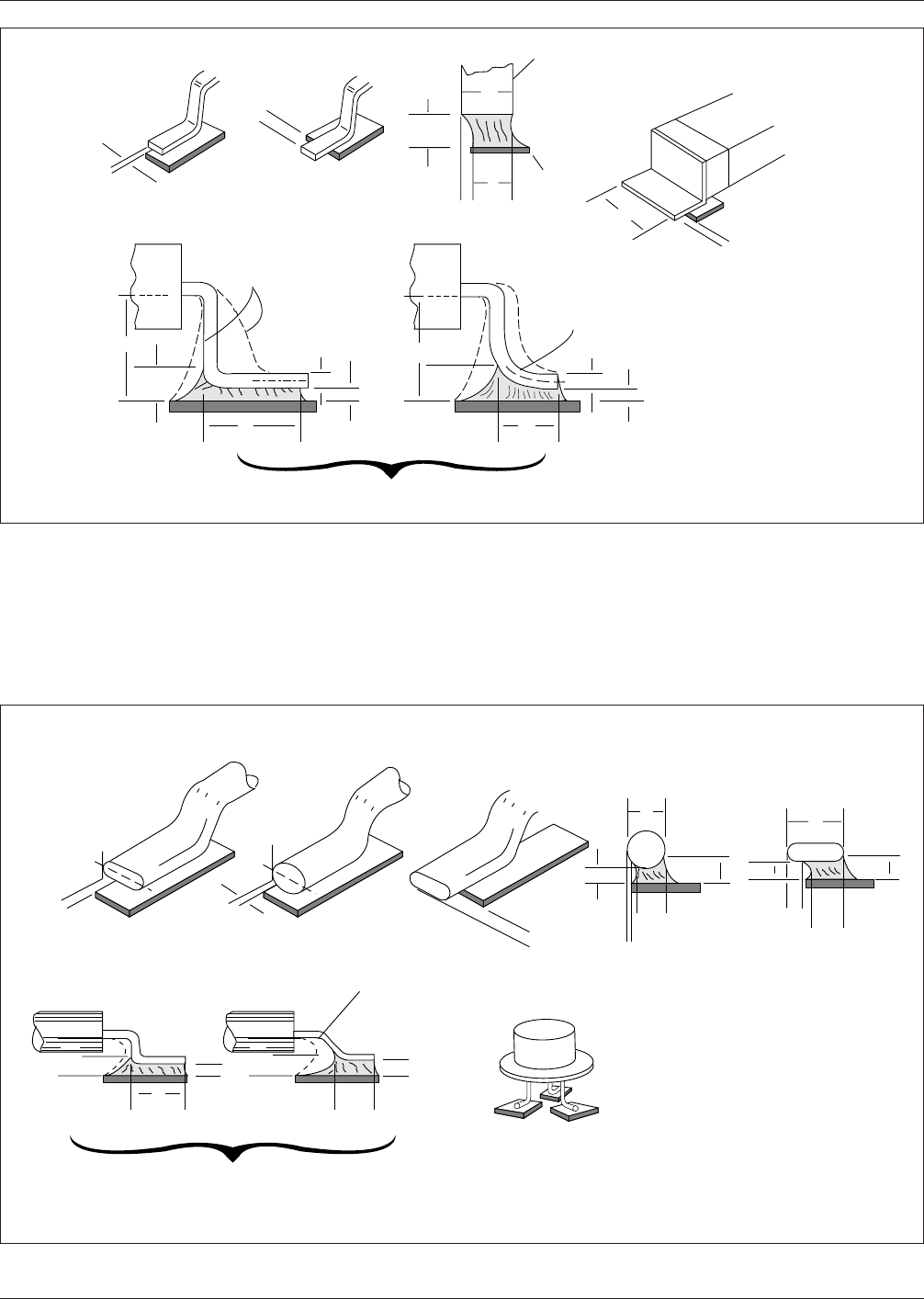
IPC-782-4-4
Figure 4–4 Flat ribbon, ‘‘L,’’ and gullwing lead joint description
B
▼
▼
A
▼
Side Overhang Toe Overhang
End Joint Width
T
▼
▼
D
▼
▼
▼
E
G
Center Line of "T"
D
▼
▼
E
▼
W = Lead Width
T = Lead Thickness
W
▼
B
▼
▼
Other Lead Configurations
▼
Side Joint Length
▼
▼
▼
▼
Lead
Land
▼
▼
▼
▼
F
▼
▼
▼
▼
CA
▼
G
▼
▼
W
T
▼
▼
▼
G
▼
F
▼
▼
▼
▼
See Note 1
Table 9–2
▼
▼
IPC-782-4-5
Figure 4–5 Round or flattened (coined) lead joint description
E
D
▼
▼
▼
▼
W = Flattened Lead
Width or Diameter
of Round Lead
T = Thickness of Lead
at Joint Site (over
land)
Side
Overhang
A
C
A
Q
G
G
C
A
B
W
▼
▼
▼
▼
Q
▼
▼
▼
▼
▼
▼
▼
▼
▼
▼
▼
Other Land
Configurations
D
▼
▼
▼
▼
▼
G
Toe
Overhang
▼
▼
A
Side Joint Length
▼
▼
▼
▼
▼
End
Joint
Width
▼
▼
W
▼
▼
▼
▼
G
E
F
▼
▼
F
▼
▼
▼
▼
See Note 1,
Table 9–3
Note: See ANSI/J-STD-001 for specific details on minimum acceptability requirements.
IPC-SM-782A December 1999
40
电子技术应用 www.ChinaAET.com
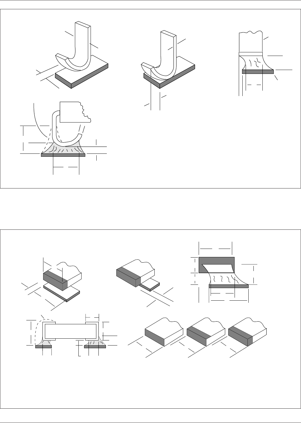
IPC-782-4-6
Figure 4–6 ‘‘J’’ lead joint description
W = Lead Width
T = Lead Thickness
▼
▼
A
▼
W
B
▼
▼
Toe
Overhang
▼
▼
C
A
▼
▼
G
▼
▼
▼
▼
F
▼
▼
E
D
▼
▼
G
See Note 1,
Table 9–4
▼
▼
Side
Overhang
T
▼
▼
End Joint Width
Side
Joint
Length
Lead
Land
▼
▼
T
▼
▼
▼
▼
IPC-782-4-7
Figure 4–7 Rectangular or square end components
W =
Width of Termination Area
•
T =
Length of Termination
•
H =
Height of Termination
•
P =
Width of Land
End
Over-
hang
Is Not
Acceptable
B
▼
▼
Three face
termination
Five face
termination
One or
Two-sided
Termination
W
Termination Configurations
▼
▼
W
▼
▼
W
▼
▼
A
Side
Over-
hang
of
Termi-
nation
▼
▼
▼
P
W
▼
P
End Joint Width
F
▼
▼
A
G
▼
▼
▼
▼
H
▼
▼
▼
▼
W
▼
▼
C
▼
▼
E
▼
▼
T
J
▼
▼
D
▼
▼
H
F
G
▼
End Overlap
▼
▼
▼
▼
▼
▼
▼
▼
▼
See Note 1
Table 9–5
Note: See ANSI/J-STD-001 for specific details on minimum acceptability requirements.
December 1999 IPC-SM-782A
41
电子技术应用 www.ChinaAET.com