Horizon UserManualV6.pdf - 第108页
18. Select Continue (F1). Continue 19. Repeat Steps 5 - 18 for the other squeegee. 20. The printer operates continuously. The menu bar displays the following options, these may be selected at any time during a print run:…
13. After the squeegee has moved approximately 20mm, select Stop Cycle (F2).
End
Run
Stop
Cycle
Paste
Load
Clean
Screen
Adjust Knead
Paste
Adjust
Inspect
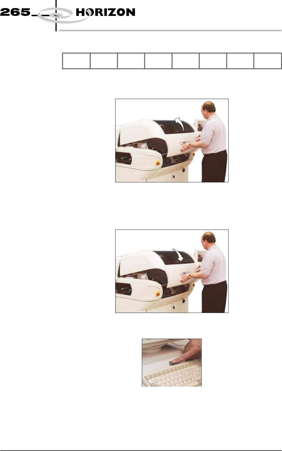
14. Lift the front printhead cover.
15. Check the deflectors are not touching the screen.
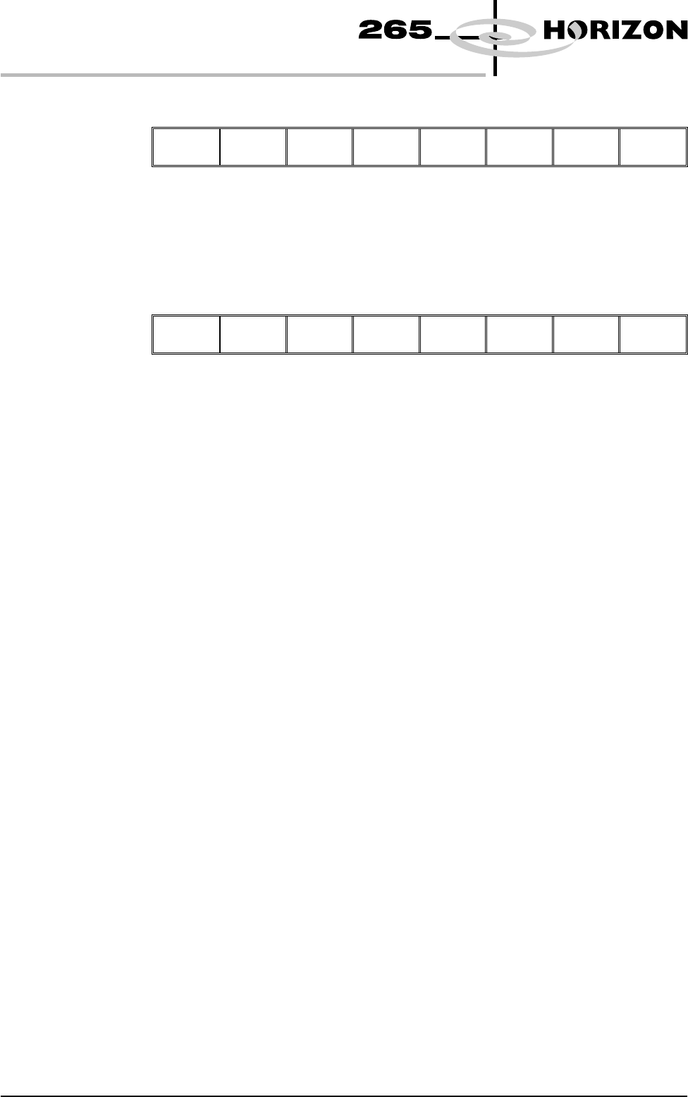
16. Lower the front printhead cover.
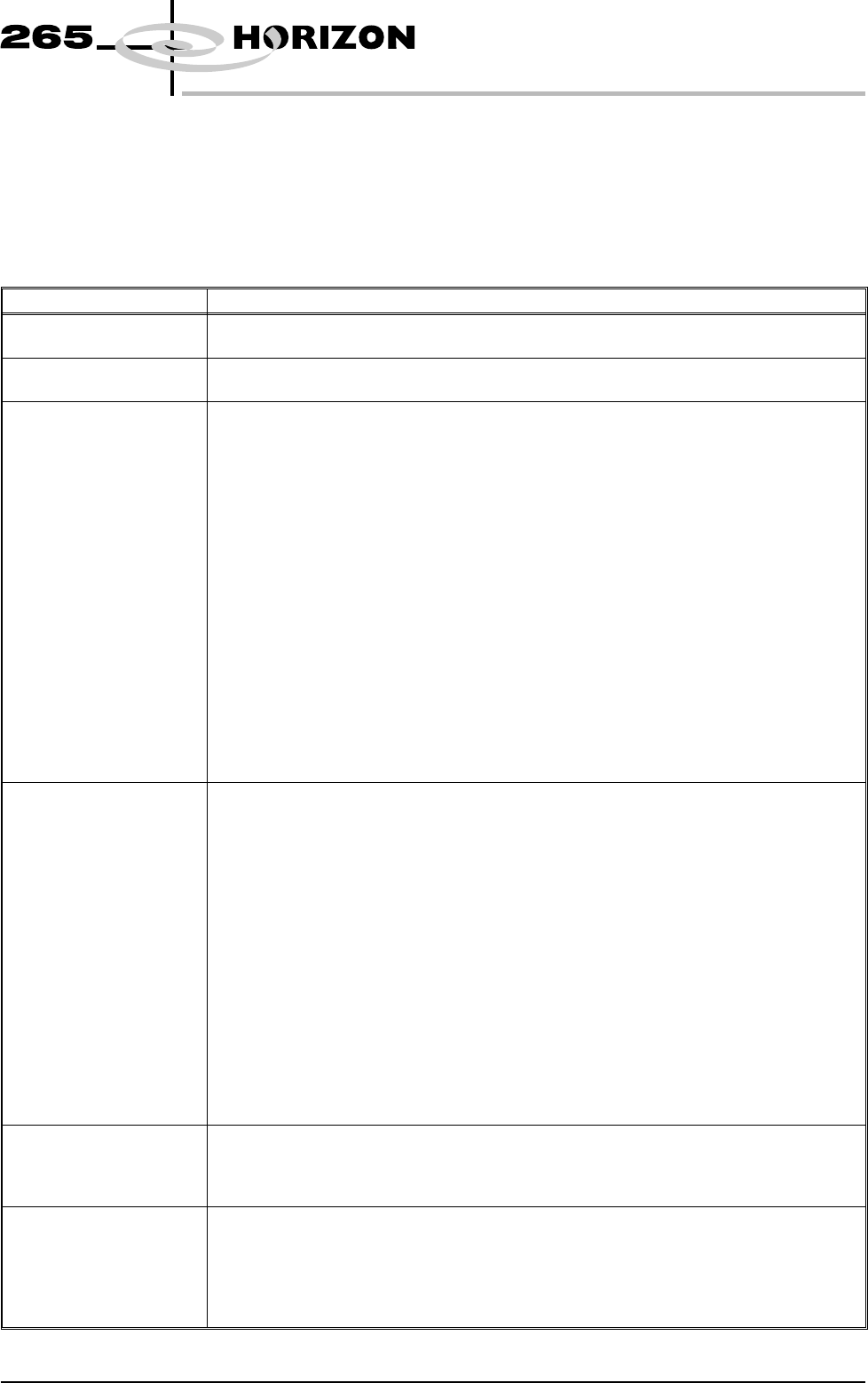
17. Press the System button.
Software Version 6 User Manual 1.91
MACHINE PROGRAMMING
STAGE 9
18. Select Continue (F1).
Continue
19. Repeat Steps 5 - 18 for the other squeegee.
20. The printer operates continuously. The menu bar displays the following
options, these may be selected at any time during a print run:
End
Run
Stop
Cycle
Paste
Load
Clean
Screen
Adjust Knead
Paste
Adjust
Inspect
End Run Selecting this option stops the printer on completion of the current print cycle.
Stop Cycle Selecting this option stops the printer immediately, halting all actions.
Paste Load Selecting this option allows the operator to load paste to the screen either
manually or automatically.
Clean Screen Selecting this option allows the operator to clean the screen in addition to the
programmed cleaning intervals.
Adjust Selecting this option allows the operator to adjust any of the main process
parameters displayed on the pop-up menu without having to access the main
menu or stop the machine.
The machine continues to run using the existing values, when Exit (F8) is
selected the new values are used.
To save the new values, select Setup (F6), select Edit Data (F3), select Save
(F2), select Exit (F8).
Knead Paste Selecting this option runs the knead paste process in addition to the programmed
cleaning intervals.
Adjust Inspect Selecting this option allows the operator to edit 2D inspection parameters.
NOTE
Global Limits, Limit Sets and Sit parameters can be edited. Site Co-ordinates
can not be adjusted. Any changes made to inspection parameters are saved on
exit.
1.92 User Manual Software Version 6
MACHINE PROGRAMMING
STAGE 9
MENU PARAMETERS
Each product has a set of parameters which are unique to that particular product
and which need to be setup to obtain acceptable printing results. These
parameters are listed below with a definition of each as an aid to machine setup.
NOTE
Machines have the ability to read product files generated by a DEK 288 printer.
Parameter Definition
Product Name The file name for the particular product. The name can consist of up to eight
alphanumeric characters with no punctuation.
Product ID The product ID is a parameter that allows a descripton of the product. This string may be
up to 32 characters long, but only the first 20 characters are displayed.
Board Length This parameter is used to set the default values for the board stop position in the X
direction, and the paste dispensing area. The maximum value depends on the type of
screen selected.
Min. Allowable 50mm (see Note 1.)
Max. Allowable
265 508mm (see Notes 1. and 2.)
255 460mm
249 430mm
Fuji 460mm
Sanyo 420mm
Heraeus 344mm
In increments of 0.1mm
NOTE
1. With remote board stop fitted
Min. Allowable 130mm
Max. Allowable 508mm (see Note 2.)
2. With the large board option the Max. Allowable is 620mm.
Although the maximum parameter is 620mm boards of 644mm can be
loaded.
Board Width This parameter sets the rail width for this particular product. It is also used to set a
default value for the print stroke, the clean screen, the board stop position in the Y
direction, and the AutoFlex rows. The maximum value depends on the screen type
selected.
Min. Allowable 50mm
Max. Allowable
265 508mm
255 432mm
249 330mm
Fuji 460mm
Sanyo 284mm
Heraeus 344mm
In increments of 0.1mm
NOTE
With remote board stop fitted
Min. Allowable 119mm
Max. Allowable 508.5mm
Board Thickness This parameter is used by the machine to set correct vision and print heights.
Minimum 0.20mm
Maximum 6.00mm
Increments 0.1mm
Underside Clearance This parameter determines the clearance provided between the underside of the board and
the top of the machine tooling to allow for components on the underside of the board.
Minimum 3mm
Maximum 42mm
Increment 0.1mm
Default 19mm
Software Version 6 User Manual 1.93
MACHINE PROGRAMMING
MENU PARAMETERS