Horizon UserManualV6.pdf - 第365页
8. Invert the ProFlow transfer head and place onto the maintenance stand (provided with the equipment). 9. Remove the paste cover from the ProFlow transfer head unit. 10. Carefully remove the wipers by loosening the six …
1. Press Setup (F6).
Run Open
Cover
Knead
Paste
Clean
Screen
Adjust
Setup
Monitor Maint.
2. Press Setup ProFlow (F4).
Mode Load
Data
Edit
Data
Setup
ProFlow
Change
Screen
Change
Tooling
Change
Language
Exit
3. Press Change ProFlow (F1).
Change
ProFlow
Load
Cassette
Prime
ProFlow
Exit
The message ‘Replace ProFlow Cover Plate then Close Cover and Press
Continue’ is displayed.
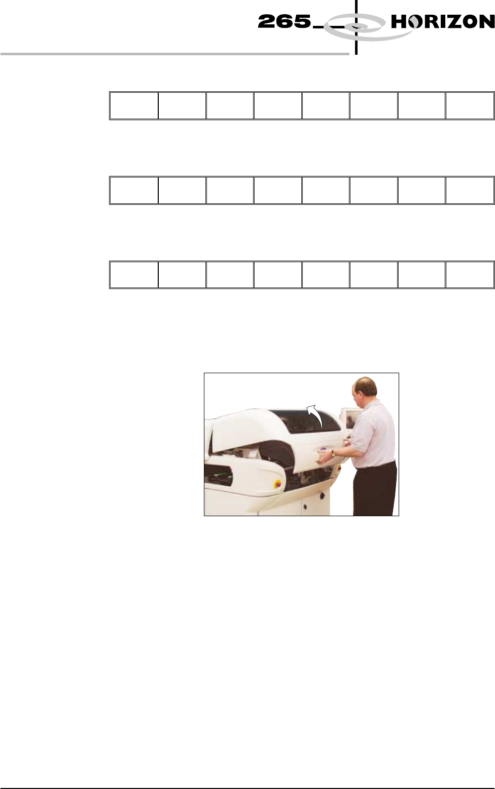
4. Open the front printhead cover.
5. Fit the paste cover to the underside of the ProFlow transfer head unit.
6. Release the latch on the front of the pressure mechanism and raise the
mechanism forwards and upwards to engage the spring locking device.
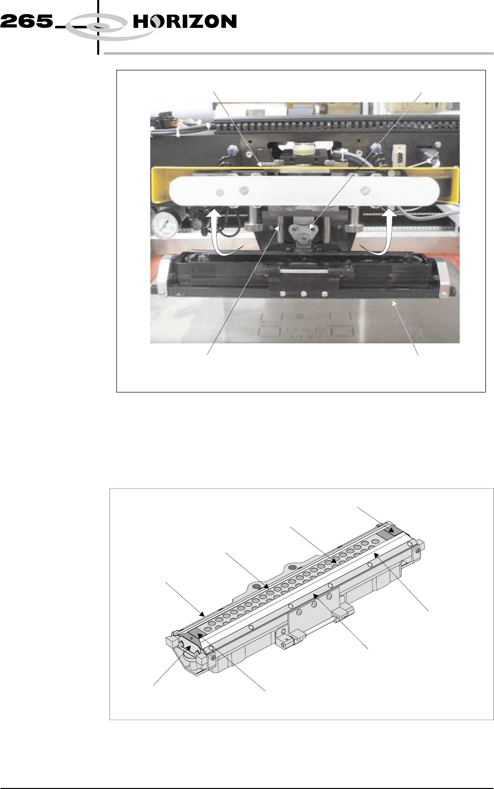
7. Turn the rotary action ‘J’ latch anti-clockwise to release the transfer head
unit from the pressure mechanism. Lift the rotary action ‘J’ latch clear of the
transfer head chassis dowel to enable the transfer head unit to be lowered
from the two interface mounting rods.
9.64 User Manual Software Version 6
CONSUMABLE REPLENISHMENTS
PROFLOW
8. Invert the ProFlow transfer head and place onto the maintenance stand
(provided with the equipment).
9. Remove the paste cover from the ProFlow transfer head unit.
10. Carefully remove the wipers by loosening the six screw securing the wiper
retaining strips.
Software Version 6 User Manual 9.65
CONSUMABLE REPLENISHMENTS
PROFLOW
Pressure Mechanism (in the Raised Position)
Rotary Action ‘J’ Latch
ProFlow Transfer Head Unit
Interface Mounting Rods (In 2 positions)
View on Front of Print Carriage
Wiper
Secondary Grid (Stainless Steel)
Wiper
Wiper Retaining Strip
Wiper Retaining Strip
End Retainer (Ski)
End Retainer (Ski)
Retainer Bracket
(in 2 Positions)
Transfer Head Inverted
11. Remove both end retainers (skis).
12. Prior to fitting replacement items ensure the area around the wipers and skis
is free from print medium deposits.
13. Fit replacement wipers into position ensuring both wipers are fully home
against the wiper securing screws.
NOTE
If fitting stepped etched wipers, ensure that the stepped edge of each wiper is
facing outwards (wiper example in figure below refers).
14. Fully tighten the wiper retaining strip screws.
15. Loosen both end retainer brackets (if fitted).
NOTE
Retainer brackets are not fitted to the rechargeable transfer head.
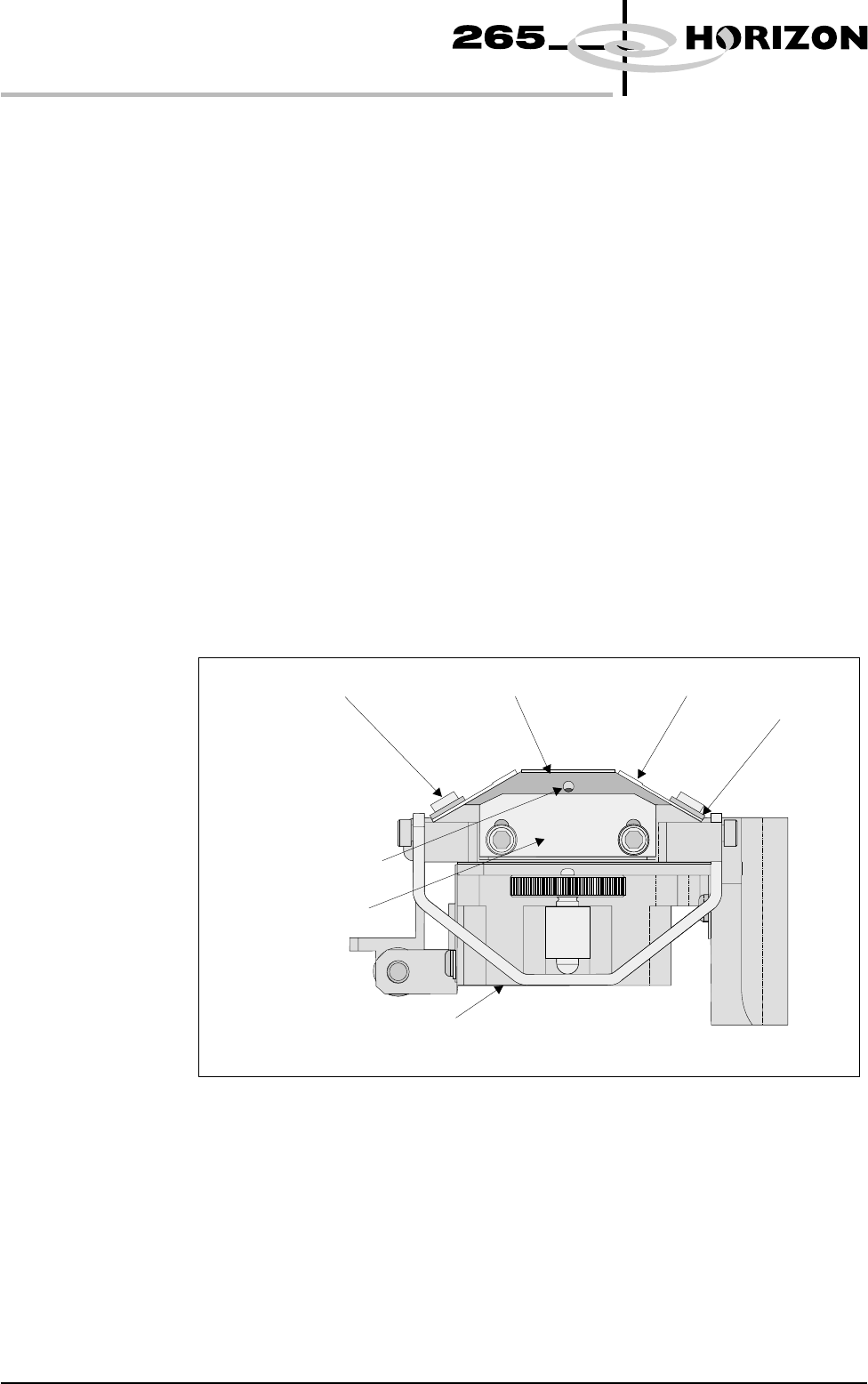
16. Slide each ski between the wipers until they are flush with the ends of the
wipers, (ensure the air escape hole on each ski faces outwards of the unit, see
figure below.)
17. Position both end retainer brackets and tighten the securing screws (if
applicable).
18. Fit the paste cover.
19. Slide the ProFlow transfer head unit onto the pressure mechanism mounting
rods and secure in place by hooking the ‘J’ rotary action latch onto the
transfer head chassis dowel pin and turn the latch clockwise.
20. Lower the pressure mechanism using the flush pull latch ensuring the
mechanism latch is engaged and is secured into place.
9.66 User Manual Software Version 6
CONSUMABLE REPLENISHMENTS
PROFLOW
Wiper Securing Screw
End Retainer (Ski)
Ski Air Escape Hole
Wiper
ProFlow Transfer Head (Inverted)
Wiper
Retaining Strip
Retainer Bracket
(if fitted)
Inverted Transfer Head (End View)