Horizon UserManualV6.pdf - 第188页
MMOV1 Group 1 (X13) MMOV1 Group 2 (X13) MMOV1 Group 3 (X13) MMOV2 Group 0 (X12) 5.6 User Manual Software Version 6 DIAGNOSTICS SYSTEM MM O V1 G roup 1 Point Description --------------------- --------- ------- -----------…
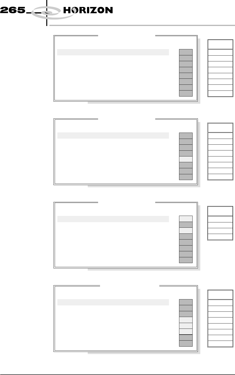
NM1 Group 2
NM1 Group 3
NM1 Group 4
MMOV1 Group 0
(X13)
Software Version 6 User Manual 5.5
DIAGNOSTICS
SYSTEM
NM 1
G
roup 2
Point Description
---------------------
---------
-------
-----------
------
Bit No
Sense
Direction
State
OFF
OFF
OFF
OFF
OFF
OFF
OFF
OFF
Board At Left
Board At Right
Not Used
Not Used
Not Used
Not Used
Board At Stop
Board Stop In
0
1
2
3
4
5
6
7
Negative
Negative
Positive
Positive
Positive
Positive
Negative
Negative
Input
Input
Input
Input
Input
Input
Input
Input
Signal
DIGIN16
DIGIN17
DIGIN18
DIGIN19
DIGIN20
DIGIN21
DIGIN22
DIGIN23
NM 1
G
roup 3
Point Description
---------------------
---------
-------
-----------
------
Bit No
Sense
Direction
State
OFF
OFF
OFF
OFF
OFF
OFF
OFF
ON
Not Used
Not Used
MIU Send Upline A
MIU Send Downline A
MIU Available Out A
Not Used
Not Used
Not Used
0
1
2
3
4
5
6
7
Positive
Positive
Positive
Positive
Positive
Positive
Positive
Positive
Output
Output
Output
Output
Output
Output
Output
Output
Signal
DOP 0
DOP 1
DOP 2
DOP 3
DOP 4
DOP 5
DOP 6
DOP 7
NM 1
G
roup 4
Point Description
---------------------
---------
-------
-----------
------
Bit No
Sense
Direction
State
OFF
ON
OFF
ON
OFF
OFF
OFF
OFF
MUX control bit 0
MUX control bit 1
MUX control bit 2
Servo Amp enable
Not Used
Not Used
Not Used
Not Used
0
1
2
3
4
5
6
7
Positive
Positive
Positive
Positive
Positive
Positive
Positive
Positive
Output
Output
Output
Output
Output
Output
Output
Output
Signal
DOP 8
DOP 9
DOP 10
DOP 11
MM
O
V1
G
roup 0
Point Description
---------------------
---------
-------
-----------
------
Bit No
Sense
Direction
State
ON
OFF
OFF
OFF
OFF
OFF
ON
ON
Right Jog Button
Left Jog Button
Not Used
Power On Monitor
Not Used
Cleaning Unit Home
Paper Low
Solvent Low
0
1
2
3
4
5
6
7
Positive
Positive
Positive
Positive
Negative
Negative
Negative
Negative
Input
Input
Input
Input
Input
Input
Input
Input
Signal
IN 0
IN 1
IN 2
IN 3
IN 4
IN 5
IN 6
IN 7
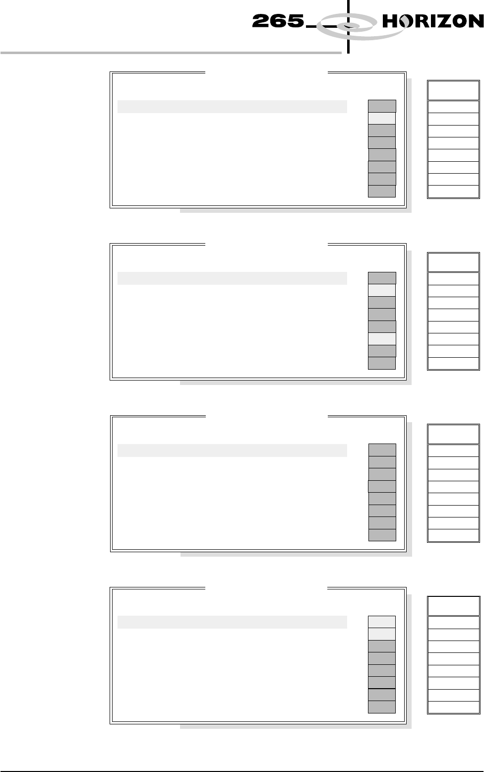
MMOV1 Group 1
(X13)
MMOV1 Group 2
(X13)
MMOV1 Group 3
(X13)
MMOV2 Group 0
(X12)
5.6 User Manual Software Version 6
DIAGNOSTICS
SYSTEM
MM
O
V1
G
roup 1
Point Description
---------------------
---------
-------
-----------
------
Bit No
Sense
Direction
State
OFF
OFF
ON
OFF
OFF
OFF
OFF
OFF
Not Used
Infinity Hardware
Not Used
Not Used
Not Used
Machine Available A
Downline Ready A
Upline Ready A
0
1
2
3
4
5
6
7
Positive
Positive
Positive
Positive
Positive
Positive
Positive
Positive
Input
Input
Input
Input
Input
Input
Input
Input
Signal
IN 8
IN 9
IN A
IN B
IN C
IN D
IN E
IN F
MM
O
V1
G
roup 2
Point Description
---------------------
---------
-------
-----------
------
Bit No
Sense
Direction
State
OFF
OFF
ON
OFF
OFF
OFF
ON
OFF
Not Used
Green Beacon
Amber Beacon
Red Beacon
Not Used
ProFlow Reg Output
Cleaner Home Clamp
Chase Clamp
0
1
2
3
4
5
6
7
Positive
Positive
Positive
Positive
Positive
Positive
Positive
Positive
Output
Output
Output
Output
Output
Output
Output
Output
Signal
Totem 0
Totem 1
Totem 2
Totem 3
Totem 4
Totem 5
Totem 6
Totem 7
MM
O
V1
G
roup 3
Point Description
---------------------
---------
-------
-----------
------
Bit No
Sense
Direction
State
OFF
OFF
OFF
OFF
OFF
OFF
OFF
OFF
Screen Clamp
Cleaner Blade
Not Used
Clamp Board
Board Stop
Not Used
Not Used
Not Used
0
1
2
3
4
5
6
7
Positive
Positive
Positive
Positive
Positive
Positive
Positive
Positive
Output
Output
Output
Output
Output
Output
Output
Output
Signal
Source 0
Source 1
Source 2
Source 3
Source 4
Source 5
Source 6
Source 7
MM
O
V2
G
roup 0
Point Description
---------------------
---------
-------
-----------
------
Bit No
Sense
Direction
State
OFF
OFF
ON
ON
OFF
OFF
OFF
OFF
Air Pressure
Screen Present
Lid Bolt Shut
Cartridge Empty
Cartridge Home
Cartridge Away
ProFlow Cassette Low
ProFlow Fitted
0
1
2
3
4
5
6
7
Positive
Positive
Positive
Positive
Negative
Negative
Positive
Positive
Input
Input
Input
Input
Input
Input
Input
Input
Signal
IN 0
IN 1
IN 2
IN 3
IN 4
IN 5
IN 6
IN 7
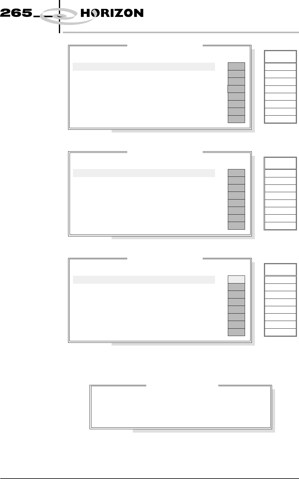
MMOV2 Group 1
(X12)
MMOV2 Group 2
(X12)
MMOV2 Group 3
(X12)
Display All
Analogue Inputs
Selecting this diagnostic function opens the following window:
Software Version 6 User Manual 5.7
DIAGNOSTICS
SYSTEM
MM
O
V2
G
roup 1
Point Description
---------------------
---------
-------
-----------
------
Bit No
Sense
Direction
State
OFF
OFF
OFF
OFF
OFF
OFF
OFF
OFF
Not Used
Not Used
ProFlow Reg Fitted
Not Used
Not Used
Not Used
Not Used
Not Used
0
1
2
3
4
5
6
7
Positive
Positive
Positive
Positive
Positive
Positive
Positive
Positive
Input
Input
Input
Input
Input
Input
Input
Input
Signal
IN 8
IN 9
IN A
IN B
IN C
IN D
IN E
IN F
MM
O
V2
G
roup 2
Point Description
---------------------
---------
-------
-----------
------
Bit No
Sense
Direction
State
OFF
OFF
OFF
OFF
OFF
OFF
OFF
OFF
Front Belt Forward
Front Belt Reverse
Rear Belt Forward
Rear Belt Reverse
Tilt Cartridge Away
Tilt Cartridge Home
Solvent Pinch Valve
Cleaner Paper Feed
0
1
2
3
4
5
6
7
Positive
Positive
Positive
Positive
Positive
Positive
Positive
Positive
Output
Output
Output
Output
Output
Output
Output
Output
Signal
Totem 0
Totem 1
Totem 2
Totem 3
Totem 4
Totem 5
Totem 6
Totem 7
MM
O
V2
G
roup 3
Point Description
---------------------
---------
-------
-----------
------
Bit No
Sense
Direction
State
OFF
OFF
OFF
ON
OFF
OFF
OFF
OFF
Release Table Brake
Cleaner Vacuum
Vacuum Valve
ProFlow Reg Control
Tooling Pressure
Lid Bolt
Dispense Paste
Solvent Tank Press
0
1
2
3
4
5
6
7
Positive
Positive
Positive
Positive
Positive
Positive
Positive
Positive
Output
Output
Output
Output
Output
Output
Output
Output
Signal
Source 0
Source 1
Source 2
Source 3
Source 4
Source 5
Source 6
Source 7
Ana
l
ogue I
/
OVa
l
ues
Description
--------------
----------------
Integer Value
--------------------
Converted Value
Pressure Sensor
Temperature
Relative Humidity
2327
3644
2985
8.51 kg
24.573 C
42.386 %
o