00198243-01_AI_BulkFeederX_XS-SX_DE+EN.pdf - 第93页
3 Retrofit kit for SX-Series 3.1 Preparatory steps on the SX-Series Assembly Instructions / Montageanleitung SIPLACE BulkFeeder X Retrofit Kit for SX Series and X Series S 07/2017 93 3 Retrofit kit for SX-Series 3.1 Prep…

2 Brief description
2.4 Required Working Time
92 Assembly Instructions / Montageanleitung SIPLACE BulkFeeder X Retrofit Kit for SX Series and X Series S 07/2017
2.4 Required Working Time
The complete installation will take approx. 8 hours.
3 Retrofit kit for SX-Series
3.1 Preparatory steps on the SX-Series
Assembly Instructions / Montageanleitung SIPLACE BulkFeeder X Retrofit Kit for SX Series and X Series S 07/2017 93
3 Retrofit kit for SX-Series
3.1 Preparatory steps on the SX-Series
► Move all component trolleys out of the machine.
► Switch off the machine, disconnect it from the
power supply and secure it to prevent
unauthorized reactivation. Observe the instruc-
tions in section 1.2 "Preparatory Work..." [}84].
► Remove all waste tape chutes and the covers on
the infrastructure box in sector 4 plus the cover
on the pneumatic unit in sector 1.
3.2 Preparatory steps
To operate the machine with a BulkFeeder X, you must retrofit both the Box PC supplied with it,
which is used as the BulkFeeder X computer, and the existing station computer.
●
Installation of a GigE card in the BulkFeeder X computer, to connect the BulkFeeder X.
●
Installation of a LAN card in the station computer of the machine, to connect the station com-
puter to the BulkFeeder X computer.
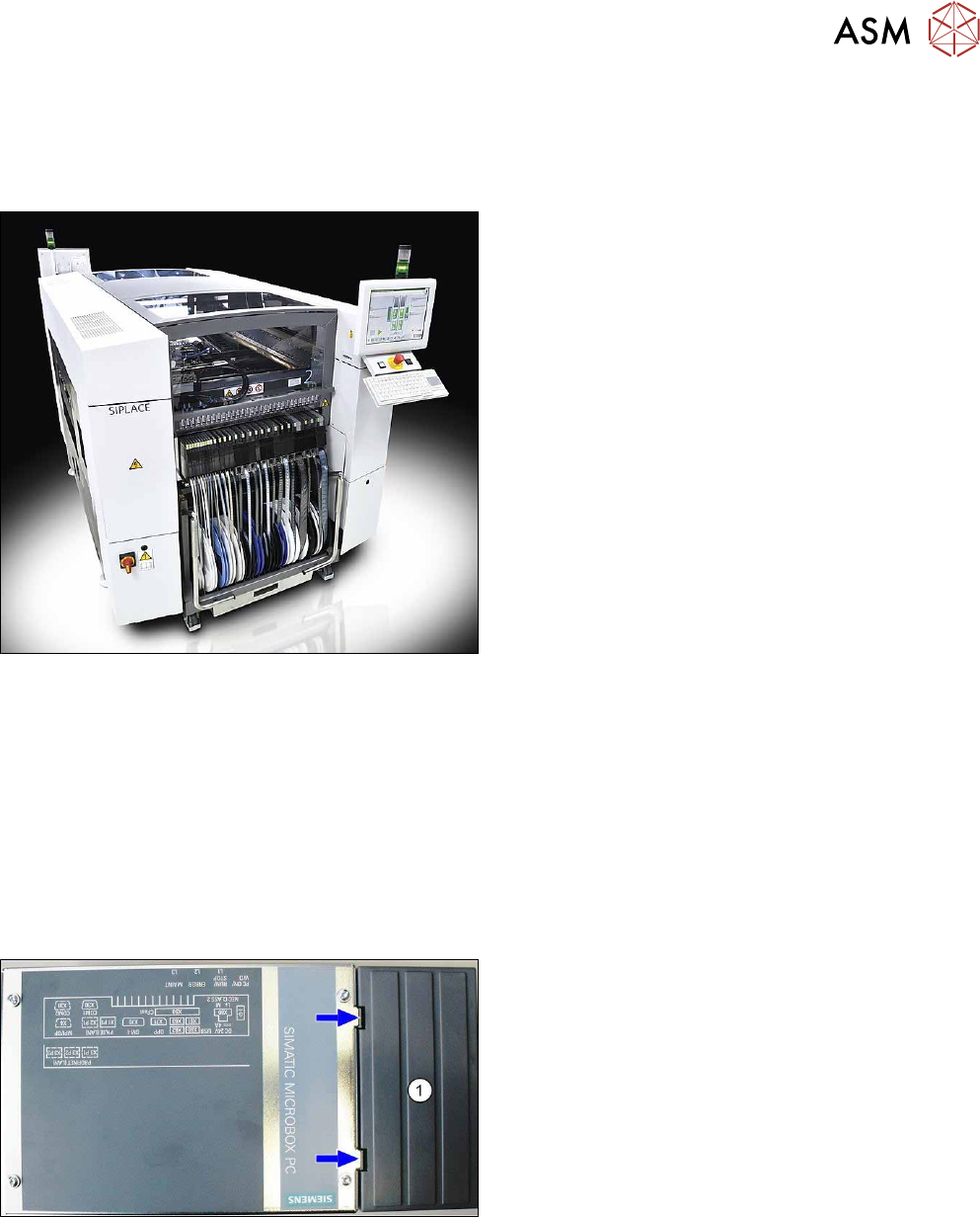
3.2.1 Installation of a GigE card in the BulkFeeder X computer
To fit the GigE card [03135985-xx] in the BulkFeeder X computer, proceed as follows:
► Release the two locks on the plastic cover (1)
and remove these.
3 Retrofit kit for SX-Series
3.2 Preparatory steps
94 Assembly Instructions / Montageanleitung SIPLACE BulkFeeder X Retrofit Kit for SX Series and X Series S 07/2017
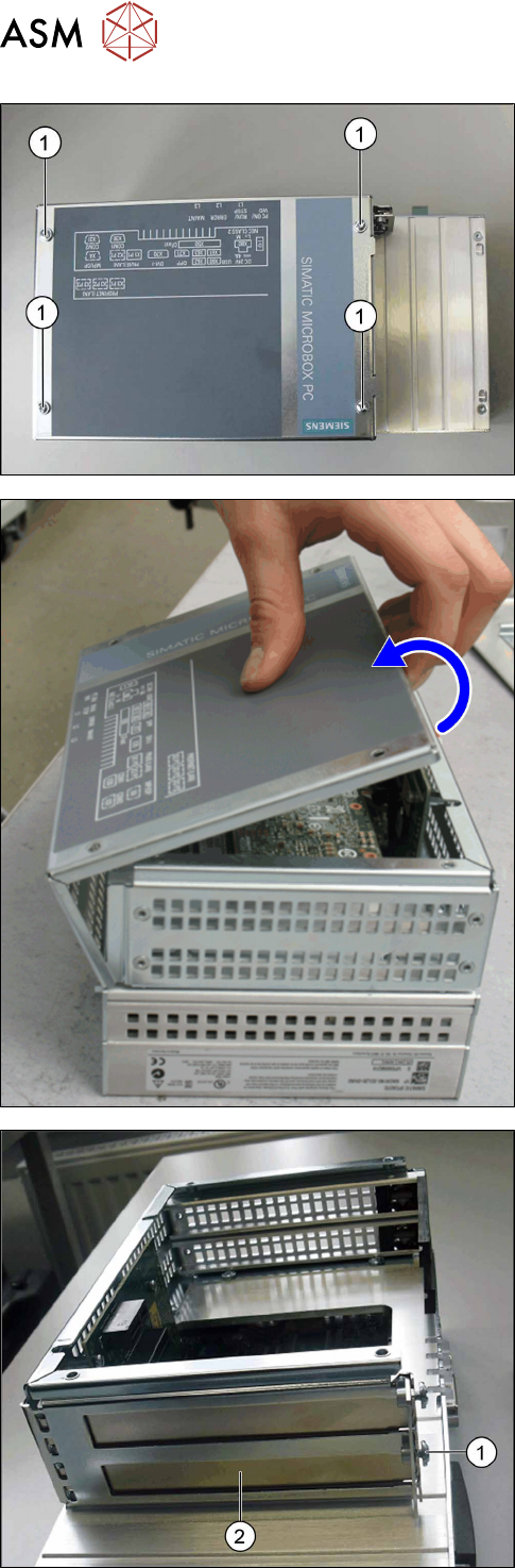
► Remove the screws (1) on the housing cover.
► Swing open the housing cover; it is held on the
folding edge by two hinges.
► Open the cover and lift it off the hinges.
► Place the cover to one side.
► Remove the screw (1) fastening the lower pro-
tective cover (2).
► Pull the protective cover off its fixtures.
► Keep the fastening screw (1). The protective
cover (2) is no longer needed.