00198243-01_AI_BulkFeederX_XS-SX_DE+EN.pdf - 第96页
3 Retrofit kit for SX-Series 3.2 Preparatory steps 96 Assembly Instructions / Montageanleitung SIPLACE BulkFeeder X Retrofit Kit for SX Series and X Series S 07/2017 ► The retrofitted computer is now ready. There are fou…
3 Retrofit kit for SX-Series
3.2 Preparatory steps
Assembly Instructions / Montageanleitung SIPLACE BulkFeeder X Retrofit Kit for SX Series and X Series S 07/2017 95
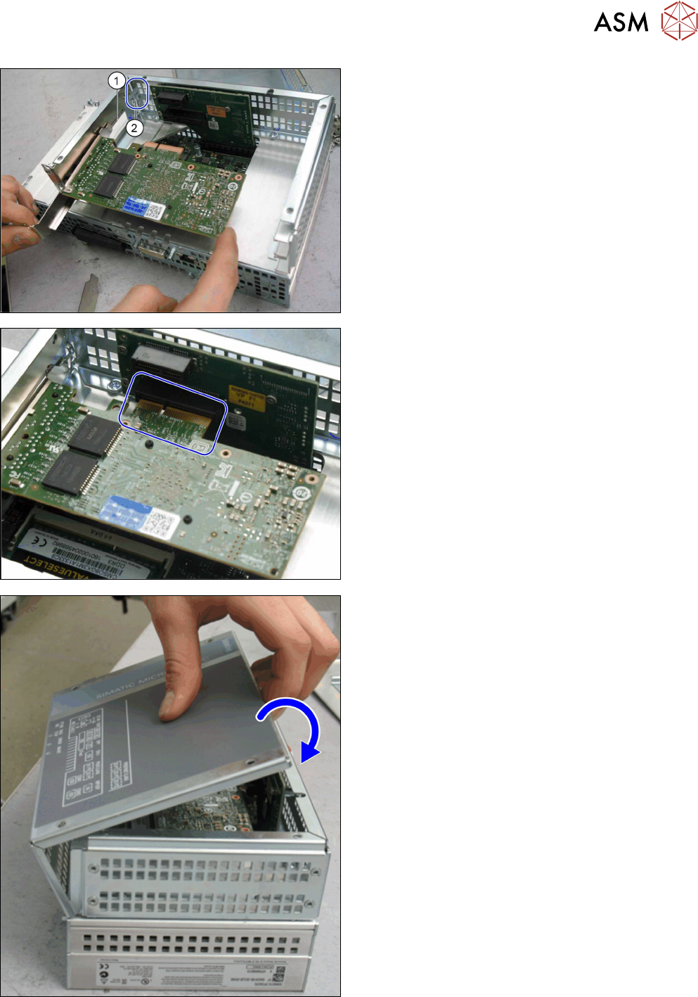
► Insert the GigE card in place of the protective
cover. Make sure that the "nib" on the guide rail
(1) correctly engages at the point where it is in-
serted (2).
► The card has a press-fit connection at the head
end. When inserting the GigE card, make sure
that this press-fit connection engages correctly
with the point opposite into which it is inserted.
► Use the fastening screw previously removed to
screw the GigE card tight.
► Close the computer: place the housing cover
back onto the hinges at the side.
► Swing the cover closed, until it engages in the
computer frame.
► Use the screws to fasten the cover.
3 Retrofit kit for SX-Series
3.2 Preparatory steps
96 Assembly Instructions / Montageanleitung SIPLACE BulkFeeder X Retrofit Kit for SX Series and X Series S 07/2017
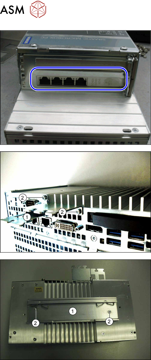
► The retrofitted computer is now ready. There are
four LAN ports for connection of the BulkFeeder
X LAN cable.
► Connection of the cable is described in the cable
instructions and in section 3.5 "Connecting the
cable" [}108].
► At the side, fit the Profibus (1) for strain relief and
the cable guidance with fastening screws (2).
► Fix the mounting rail (1) into place, with the
fastening screws (2). This facilitates subsequent
installation of the BulkFeeder X computer on the
mounting plate in the infrastructure box at loca-
tion 1.
3 Retrofit kit for SX-Series
3.2 Preparatory steps
Assembly Instructions / Montageanleitung SIPLACE BulkFeeder X Retrofit Kit for SX Series and X Series S 07/2017 97
3.2.2 Fitting the LAN card in the station computer
In order to fit the LAN card in the station computer, you need to remove the station computer from
the machine.
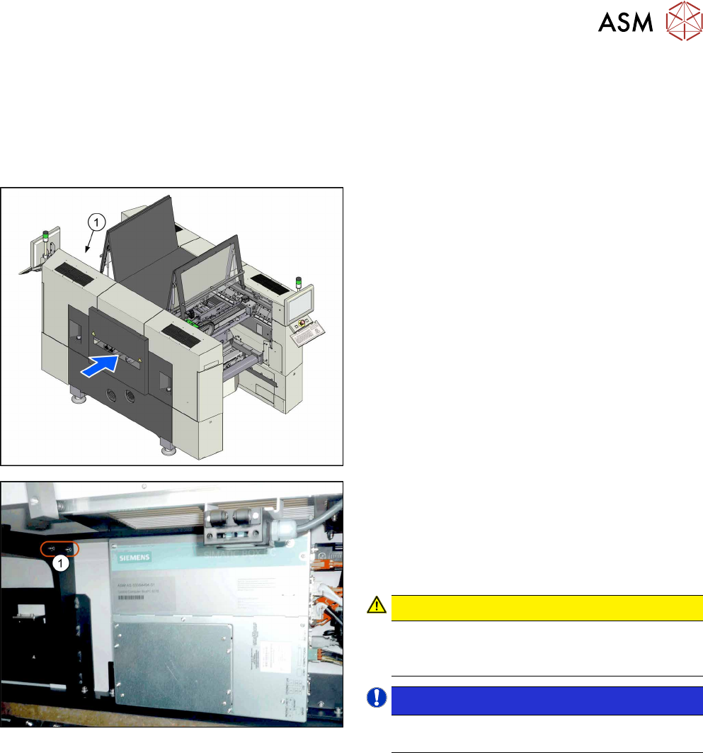
3.2.2.1 Removing the station computer
To remove the station computer, proceed as follows:
► The station computer (1) is located at the top
right of location 2.
► Unplug all press-fit connections to the station
computer. Mark their positions, to make clear as-
signment easier later on.
► Remove the screws (1) fastening the fixture
bracket for the station computer. You can now
swing the station computer down and away.
CAUTION!
Magnets (magnetic force 400Nm)
Make sure that you do not move the station com-
puter too near to the magnets.
.
NOTICE!
The station computer has rubber feet on its
base. These sit in special recesses.
.
► Unscrew the fixture bracket from the station com-
puter.